Thursday, January 12, 2012

CCDA 640-864 Official Cert Guide - Chapter 12 Summary


Network Security Overview
U.S. Public Company Accounting Reform and Investor Protection Act of 2002 (Sarbanes-Oxley or SOX): Focuses on the accuracy and controls imposed on a company’s financial records. This was passed as a U.S. federal law because of a number of corporate and accounting scandals.

Payment Card Industry (PCI) Data Security Standard (DSS): PCI is a data security standard that defines how to protect credit card holder data, including the storage and transfer of credit card holder information. Many retailers that accept credit cards have to meet PCI DSS standards or pay stiff penalties and are subject to regular and rigorous audits for PCI DSS compliance.

Gramm-Leach-Bliley Financial Services Modernization Act of 1999 (GLBA): Provides protection against the sale of bank and account information that is regularly bought and sold by financial institutions. GLBA also guards against the practice of obtaining private information through false pretenses.

U.S. Health Insurance Portability and Accountability Act (HIPAA): Applies to the protection of private health information that is used electronically. The purpose is to enable better access to health information, reduce fraud, and lower the cost of health care in the United States.

EU Data Protection Directive 95/46/EC: Calls for the protection of people’s right to privacy with respect to the processing of personal data.
Reconnaissance: The goal of reconnaissance is to gather as much information as possible about the target host/network. Generally, this type of information gathering is done before an attack is carried out.

Gaining unauthorized access: Refers to the act of attacking or exploiting the target system or host. Operating systems, services, and physical access to the target host have known system vulnerabilities that the attacker can take advantage of and use to increase his or her privileges. Social engineering is another technique for obtaining confidential information from employees by manipulation. As a result of the attacker exploiting the host, confidential information can be read, changed, or deleted from the system.

Denial of service (DoS): DoS attacks aim to overwhelm resources such as memory, CPU, and bandwidth and thus impact the target system and deny legitimate user’s access. Distributed DoS (DDoS) attacks involve multiple sources working together to deliver the attack.

Feature Description
Feature
Verifies DHCP transitions and prevents rogue DHCP server from interfering with production traffic
DHCP snooping

Intercepts Address Resolution Protocol (ARP) packets and verifies that the packets have valid IP-to-MAC bindings
Dynamic ARP Inspection
(DAI)
Prevents unknown source addresses from using the network as a transport mechanism to carry out attacks
Unicast Reverse Path Forwarding (uRFP)

Controls what traffic is allowed on the network
Access control lists (ACL)

Controls the rate of bandwidth that incoming traffic, such as
ARP packets and DHCP requests
Rate limiting


When attackers change sensitive data without the proper authorization, this is called an integrity violation.

Confidentiality breaches occur when the attacker attempts to read sensitive information.

Security Policy and Process
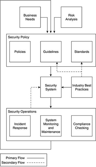


Basic Approach of a Security Policy:
To help create a security policy, here is generally accepted approach from RFC 2196:
Step 1. Identify what you are trying to protect.
Step 2. Determine what you are trying to protect it from.
Step 3. Determine how likely the threats are.
Step 4. Implement measures that protect your assets in a cost-effective manner.
Step 5. Review the process continuously, and make improvements each time a weakness is found


PKI
  • It relies on asymmetric cryptography, which uses two different keys for encryption.
  • Public keys are used to encrypt and private keys to decrypt.
  • PKI requires a certificate to be issued by a certificate authority (CA) and is used by many e-commerce sites on the Internet.

VPN Description
VPN Name
Use AH and ESP to secure data; requires endpoints have IPsec software
Standard IPsec

Secure encrypted point-to-point GRE tunnels; on-demand spoke-to-spoke connectivity
Cisco DMVPN

Simplifies hub-and-spoke VPNs; need to reduce VPN management
Cisco Easy VPN
Enables routing and multicast traffic across an IPsec VPN; non-IP protocol and QoS support
Cisco GRE-based VPN
Encryption integration on IP and MPLS WANs; simplifies encryption
management using group keying; any-to-any connectivity
Cisco GET VPN


The IPsec suite is an open standard. IPsec uses the following protocols to perform various functions:
  • Authentication Headers (AH) provide connectionless integrity and data origin authentication for IP datagram’s and provides protection against replay attacks.
  • Encapsulating Security Payloads (ESP) provide confidentiality, data origin authentication, connectionless integrity, an anti-replay service (a form of partial sequence integrity), and limited traffic flow confidentiality.


Tuesday, January 10, 2012

CCDA 640-864 Official Cert Guide - Chapter 11 Summary


OSPFv2 Areas

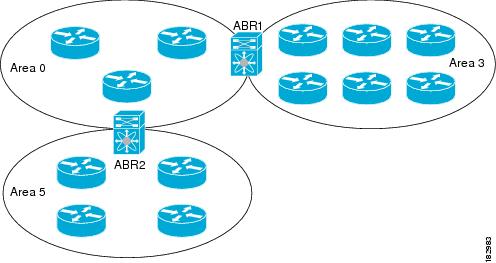
You can limit the CPU and memory requirements that OSPFv2 puts on the routers by dividing an OSPFv2 network into areas. An area is a logical division of routers and links within an OSPFv2 domain that creates separate subdomains. LSA flooding is contained within an area, and the link-state database is limited to links within the area. You can assign an area ID to the interfaces within the defined area. The Area ID is a 32-bit value that you can enter as a number or in dotted decimal notation, such as 10.2.3.1.
If you define more than one area in an OSPFv2 network, you must also define the backbone area, which has the reserved area ID of 0. If you have more than one area, then one or more routers become area border routers (ABRs). An ABR connects to both the backbone area and at least one other defined area.


Stub Area
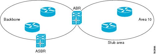
You can limit the amount of external routing information that floods an area by making it a stub area. A stub area is an area that does not allow AS External (type 5) LSAs. These LSAs are usually flooded throughout the local autonomous system to propagate external route information. Stub areas have the following requirements:
•All routers in the stub area are stub routers.
•No ASBR routers exist in the stub area.
•You cannot configure virtual links in the stub area.


Stub areas use a default route for all traffic that needs to go through the backbone area to the external autonomous system. The default route is 0.0.0.0 for IPv4.

Not-So-Stubby Area
A Not-so-Stubby Area (NSSA) is similar to a stub area, except that an NSSA allows you to import autonomous system external routes within an NSSA using redistribution. The NSSA ASBR redistributes these routes and generates NSSA External (type 7) LSAs that it floods throughout the NSSA. You can optionally configure the ABR that connects the NSSA to other areas to translate this NSSA External LSA to AS External (type 5) LSAs. The ABR then floods these AS External LSAs throughout the OSPFv2 autonomous system. The backbone Area 0 cannot be an NSSA.


OSPF Router Types

The ABR has a separate link-state database for each area to which it connects. The ABR sends Network Summary (type 3) LSAs from one connected area to the backbone area. The backbone area sends summarized information about one area to another area.
OSPFv2 defines one other router type: the autonomous system boundary router (ASBR). This router connects an OSPFv2 area to another autonomous system. An autonomous system is a network controlled by a single technical administration entity. OSPFv2 can redistribute its routing information into another autonomous system or receive redistributed routes from another autonomous system.

LSA Types

Type
Name
Description
1
Router LSA
LSA sent by every router. This LSA includes the state and the cost of all links and a list of all OSPFv2 neighbors on the link. Router LSAs trigger an SPF recalculation. Router LSAs are flooded to local OSPFv2 area.
2
Network LSA
LSA sent by the DR. This LSA lists all routers in the multi-access network. Network LSAs trigger an SPF recalculation.
3
Network Summary LSA
LSA sent by the area border router to an external area for each destination in the local area. This LSA includes the link cost from the area border router to the local destination.
4
ASBR Summary LSA
LSA sent by the area border router to an external area. This LSA advertises the link cost to the ASBR only.
5
AS External LSA
LSA generated by the ASBR. This LSA includes the link cost to an external autonomous system destination. AS External LSAs are flooded throughout the autonomous system.
7
NSSA External LSA
LSA generated by the ASBR within a not-so-stubby area (NSSA). This LSA includes the link cost to an external autonomous system destination. NSSA External LSAs are flooded only within the local NSSA.
9-11
Opaque LSAs
LSA used to extend OSPF.


OSPFv2 Summary
OSPFv2 is used in large enterprise IPv4 networks. The network topology must be hierarchy. The characteristics of OSPFv2 follow:
  • Link-state routing protocol.
  • Uses IP protocol 89.
  • Classless protocol (supports VLSMs and CIDR).
  • Metric is cost (based on interface bandwidth by default).
  • Fast convergence. Uses link-state updates and SPF calculation.
  • Reduced bandwidth use. Sends partial route updates only when changes occur.
  • Routes are labeled as intra-area, interarea, external Type 1, or external Type 2.
  • Support for authentication.
  • Uses the Dijkstra algorithm to calculate the SPF tree.
  • Default administrative distance is 110.
  • Uses multicast address 224.0.0.5 (ALLSPFRouters).
  • Uses multicast address 224.0.0.6 (ALLDRouters).
  • Good scalability. Recommended for large networks.

OSPFv3 Changes from OSPFv2:
The following are the major changes for OSPFv3:
  • Version number is 3: Obviously, this is a newer version of OSPF, and it runs over IPv6 only.
  • Support for IPv6 addressing: New LSAs created to carry IPv6 addresses and prefixes.
  • Per-link processing: OSPFv2 uses per-subnet processing. With link processing, routers in the same link can belong to multiple subnets.
  • Address semantics removed: Addresses are removed from the router and network LSAs. These LSAs now provide topology information.
  • No authentication in the OSPFv3 protocol: schemes inherited in IPv6.
  • New link LSA: For local-link flooding scope.
  • New intra-area-prefix LSA: Carries all the IPv6 prefix information. Similar to OSPFv2 router and network LSAs.
  • Identifying neighbors by router ID: Neighbors are always identified by the router ID. This does not occur in OSPFv2 point-to-point and broadcast networks.
  • Options field changes: Two Options bits, the R-bit and the V6-bit, have been added to the Options field for processing router LSAs during the SPF calculation.

OSPFv3 LSA Types


Router LSA:
Each OSPF router originates Router LSAs indicating the state and cost of the router's interfaces to the area. Router LSAs are flooded throughout the single area only.
A router may originate one or more Router LSAs, distinguished by their Link State IDs. The receiving router concatenates the Router LSAs if it receives more than one Router LSA from a single router.
The Router LSA indicates if the router is an ASBR or an ABR or if it is one end-point of a virtual link. These LSAs have no address information.


Network LSA:
Network LSAs are originated by the DR for a broadcast or NBMA network in the area which supports two or more routers. The LSA describes all routers connected to the link, including the DR. The LSA's Link State ID field is set to the Interface ID that the DR has been using in Hello packets. No address information is carried in the Network LSA.


Inter-Area Prefix LSA:
These LSAs are IPv6 equivalent of IPv4's Type-3 Summary LSAs. These LSAs are originated by the ABR to specify IPv6 prefixes that belong to other areas. A separate LSA is originated for each address prefix.
For Stub areas, the Inter-area Prefix LSA is used to describe a default route. The prefix length of the default route is set to 0.


Inter-Area Router LSA:
These LSAs are IPv6 equivalent of IPv4's Type-4 Summary LSAs. Originated by the ABR, the Inter-Area Router LSA describes the route to the ASBR. Each LSA describes a route to a single router.


AS-External LSA:
These LSAs are IPv6 equivalent of IPv4's Type-5 External LSAs. These LSAs are originated by ASBRs describing the destinations external to the AS. Each LSA describe a route to a single IPv6 prefix external to the AS.
AS-External LSAs can be used to describe a default route. Default routes are used when no specific route exists for a destination.


Link LSA:
A router originates a separate Link LSA for each link it is attached to. These LSAs have link-local flooding scope and are never flooded beyond a link that they are associated with. These LSAs have three purposes-
    - notify the link-local address of the router's interface to the routers attached to the link
    - inform other routers attached to the link of the list of IPv6 prefixes to associate with the link
    - allow the router to assert the collection of Option bits to associate with the Network LSA that will be originated for the link.
The Link-State ID is set to the Interface ID of link of the originating router.


Intra-Area Prefix LSA:

A router uses Intra-Area Prefix LSA to advertise IPv6 prefixes that are associated with
    a) the router itself (in IPv4, this was carried in Router LSA)
    b) an attached stub network segment (in IPv4, this was carried in Router LSA)
    c) an attached transit network segment (in IPv4, this was carried in Network LSA)
A router can originate multiple Intra-Area Prefix LSAs for each router or transit network; each LSA is distinguished by its Link State ID.


Options field:
The 24-bit Options field is included in Hello and DBD packets, and Router, Network and Inter-area Router LSAs. It enables OSPF routers to support optional capabilities, and to communicate their capabilities to other OSPF routers in the network. 


OSPFv3 Summary
OSPFv3 is used in large enterprise IPv6 networks. The network topology must be hierarchical. OSPF is used in the enterprise campus building access, distribution, and core layers. OSPF is also used in the enterprise data center, WAN/MAN, and branch offices.
The characteristics of OSPFv3 follow:
  • Link-state routing protocol for IPv6.
  • Uses IPv6 Next Header 89.
  • Metric is cost (based on interface bandwidth by default).
  • Sends partial route updates only when changes occur.
  • Routes are labeled as intra-area, interarea, external Type 1, or external Type 2.
  • Uses IPv6 for authentication.
  • Uses the Dijkstra algorithm to calculate the SPF tree.
  • Default administrative distance is 110.
  • Uses multicast address FF02::5 (ALLSPFRouters).
  • Uses multicast address FF02::6 (ALLDRouters).
  • Fast convergence, scalable, and reduces bandwidth.
  • Recommended for large IPv6 networks.

BGP Summary
The characteristics of BGP follow:
  • BGP is an Exterior Gateway Protocol (EGP) used in routing in the Internet. It is an interdomain routing protocol.
  • BGP is a path-vector routing protocol suited for strategic routing policies.
  • It uses TCP port 179 to establish connections with neighbors.
  • BGPv4 implements CIDR.
  • eBGP is used for external neighbors. It is used between different autonomous systems.
  • iBGP is used for internal neighbors. It is used within an autonomous system.
  • BGP uses several attributes in the routing-decision algorithm.
  • It uses confederations and route reflectors to reduce BGP peering overhead.

Route Manipulation

            PBR
            Route Summarization
            Route Redistribution
            Route Filtering
           

IP Multicast Review


IGMP

IGMP is a standard defined in RFC1112 for IGMPv1, in RFC2236 for IGMPv2 and in RFC3376 for IGMPv3. IGMP specifies how a host can register with a router in order to receive specific multicast traffic. 


CGMP

CGMP was first implemented by Cisco to restrain multicast traffic in a L2 network. Because a switch is, by essence, not capable of looking at L3 packets, it cannot distinguish an IGMP packet. With CGMP, the router provides the interface between the hosts. The routers "talk" IGMP, and the switches "talk" CGMP.


IGMP Snooping

IGMP snooping is another feature that allows you to directly capture IGMP frames. 
IGMP snooping, as implied by the name, is a feature that allows the switch to "listen in" on the IGMP conversation between hosts and routers. When a switch hears an IGMP report from a host for a given multicast group, the switch adds the host's port number to the GDA list for that group. And, when the switch hears an IGMP Leave, it removes the host's port from the CAM table entry.


Sparse Versus Dense Multicast 

The Dense approach assumes that the multicast group members are densely distributed throughout the network (many of the subnets contain at least one group member), all devices want to receive multicast traffic, and that bandwidth is plentiful. The Sparse approach to multicast routing assumes that multicast group members are sparsely distributed throughout the network, assumes received do not want to receive multicast traffic, and that bandwidth is not necessarily widely available.

Multicast Source and Shared Trees 

With source trees, the tree roots from the source of the multicast group and then expands throughout the network in spanning-tree fashion to the destination hosts. Source trees are also called shortest-path trees (SPT) because they create paths without having to go through a rendezvous point (RP).
Shared trees create the distribution tree’s root somewhere between the network’s source and receivers. The root is called the RP. The tree is created from the RP in spanning-tree fashion with no loops.

PIM 

PIM comes in two flavors: sparse mode (PIM-SM) and dense mode (PIM-DM). The first uses shared trees and RPs to reach widely dispersed group members with reasonable protocol bandwidth efficiency. The second uses source trees and reverse path forwarding (RPF) to reach relatively close group members with reasonable processor and memory efficiency in the network devices of the distribution trees.

DVMRP 

RFC 1075 describes DVMRP. It is the primary multicast routing protocol used in the multicast backbone (MBONE). The MBONE is used in the research community.


CCDA 640-864 Official Cert Guide - Chapter 10 Summary


Routing Protocol Characteristics
  • Distance-vector, link-state, or hybrid: How routes are learned
  • Interior or exterior: For use in private networks or the public Internet
  • Classless (classless interdomain routing [CIDR] support) or classful: CIDR enables aggregation of network advertisements (supernetting) between routers
  • Fixed-length or variable-length subnet masks (VLSM): Conserve addresses within a network
  • Flat or hierarchical: Addresses scalability in large internetworks
  • IPv4 or IPv6: Newer routing protocols are used for IPv6 networks

IPv4 Routing Protocols
IPv6 Routing Protocols
RIPv2
RIPng
EIGRP
EIGRP for IPv6
OSPFv2
OSPFv3
IS-IS
IS-IS for IPv6
BGP
Multiprotocol BGP


Default Administrative Distances for IP Routes

Routing Loop-Prevention Schemes:
Some routing protocols employ schemes to prevent the creation of routing loops in the network. These schemes are:


  • Split horizon
Split Horizon
Split horizon helps reduce convergence time by not allowing routers to advertise networks in the direction from which those networks were learned. The only information sent in RIP announcements are for those networks that are beyond the neighboring router in the opposite direction. Networks learned from the neighboring router are not included.
Split horizon eliminates count-to-infinity and routing loops during convergence in single-path internetworks and reduces the chances of count-to-infinity in multi-path internetworks. Figure 6 illustrates how split horizon keeps the RIP router from advertising routes in the direction from which they were learned.


  • Poison reverse
Split Horizon with Poison Reverse
Split horizon with poison reverse differs from simple split horizon because it announces all networks. However, those networks learned in a given direction are announced with a hop count of 16, indicating that the network is unreachable. In a single-path internetwork, split horizon with poison reverse has no benefit beyond split horizon. However, in a multi-path internetwork, split horizon with poison reverse greatly reduces count-to-infinity and routing loops. Count-to-infinity can still occur in a multi-path internetwork because routes to networks can be learned from multiple sources.
In Figure 7, split horizon with poison reverse advertises learned routes as unreachable in the direction from which they are learned. Split horizon with poison reverse does have the disadvantage of additional RIP message overhead because all networks are advertised.


  • Counting to infinity
The Count-to-Infinity Problem
The classic distance vector convergence problem is known as the count-to-infinity problem and is a direct result of the asynchronous announcement scheme. When RIP for IP routers add routes to their routing table, based on routes advertised by other routers, they keep only the best route in the routing table and they update a lower cost route with a higher cost route only if is being announced by the same source as the current lower cost route. In certain situations, as illustrated in Figures 1 through 5, this causes the count-to-infinity problem.
Assume that the internetwork in Figure 1 has converged. For simplicity, the announcements sent by Router 1 on Network 1 and Router 2 on Network 3 are not included.

Figure 1: Converged Internetwork
Now assume that the link from Router 2 to Network 3 fails and is sensed by Router 2. As shown in Figure 2, Router 2 changes the hop count for the route to Network 3 to indicate that it is unreachable, an infinite distance away. For RIP for IP, infinity is 16.

Figure 2: Link to Network 3 Fails
However, before Router 2 can advertise the new hop count to Network 3 in a scheduled announcement, it receives an announcement from Router 1. The Router 1 announcement contains a route to Network 3 which is 2 hops away. Because 2 hops away is a better route than 16 hops, Router 2 updates its routing table entry for Network 3, changing it from 16 hops to 3 hops, as shown in Figure 3.

Figure 3: Router 2 After Receiving Announcement From Router 1
When Router 2 announces its new routes, Router 1 notes that Network 3 is available 3 hops away through Router 2. Because the route to Network 3 on Router 1 was originally learned from Router 2, Router 1 updates its route to Network 3 to 4 hops. (See Figure 4.)

Figure 4: Router 1 After Receiving Announcement From Router 2
When Router 1 announces its new routes, Router 2 notes that Network 3 is available 4 hops away through Router 1. Because the route to Network 3 on Router 2 was originally learned from Router 1, Router 2 updates its route to Network 3 to 5 hops. (See Figure 5.)

Figure 5: Router 2 After Receiving Another Announcement from Router 1
The two routers continue to announce routes to Network 3 with higher and higher hop counts until infinity (16) is reached. Then, Network 3 is considered unreachable and the route to Network 3 is eventually timed out of the routing table. This is known as the count-to-infinity problem.
The count-to-infinity problem is one of the reasons why the maximum hop count of RIP for IP internetworks is set to 15 (16 for unreachable). Higher maximum hop count values would make the convergence time longer when count-to-infinity occurs. Also note that during the count-to-infinity in the previous example, the route from Router 1 to Network 3 is through Router 2. The route from Router 2 to Network 3 is through Router 1. A routing loop exists between Router 1 and Router 2 for Network 3 for the duration of the count-to-infinity problem.

RIPv2 Summary
The characteristics of RIPv2 follow:
  • Distance-vector protocol.
  • Uses UDP port 520.
  • Classless protocol (support for CIDR).
  • Supports VLSMs.
  • Metric is router hop count.
  • Low scalability: maximum hop count is 15; infinite (unreachable) routes metric of 16.
  • Periodic route updates are sent every 30 seconds to multicast address 224.0.0.9.
  • 25 routes per RIP message (24 if you use authentication).
  • Supports authentication.
  • Implements split horizon with poison reverse.
  • Implements triggered updates.
  • Subnet mask included in route entry.
  • Administrative distance for RIPv2 is 120.
  • Not scalable. Used in small, flat networks or at the edge of larger networks.

RIPng Summary
  • The characteristics of RIPng are as follows:
  • Distance-vector protocol for IPv6 networks only.
  • Uses UDP port 521.
  • Metric is router hop count.
  • Maximum hop count is 15; infinite (unreachable) routes have a metric of 16.
  • Periodic route updates are sent every 30 seconds to multicast address FF02::9.
  • Uses IPv6 functions for authentication.
  • Implements split horizon with poison reverse.
  • Implements triggered updates.
  • Prefix length included in route entry.
  • Administrative distance for RIPv2 is 120.
  • Not scalable. Used in small networks.

EIGRP for IPv4 Summary
The characteristics of EIGRP for IPv4 networks follow:
  • Hybrid routing protocol (a distance-vector protocol that has link-state protocol characteristics).
  • Uses IP protocol number 88.
  • Classless protocol (supports VLSMs).
  • Default composite metric uses bandwidth and delay.
  • You can factor load and reliability into the metric.
  • Sends partial route updates only when there are changes.
  • Supports MD5 authentication.
  • Uses DUAL for loop prevention.
  • Fast convergence.
  • By default, equal-cost load balancing with equal metrics. Unequal-cost load sharing with the variance command.
  • Administrative distance is 90 for EIGRP internal routes, 170 for EIGRP external routes, and 5 for EIGRP summary routes.
  • High scalability; used in large networks.
  • Multicasts updates to 224.0.0.10.
  • Does not require a hierarchical physical topology.
  • Provides routing for IPv4, plus legacy protocols such as AppleTalk and IPX.
  
EIGRP for IPv6 Summary
The characteristics of EIGRP for IPv6 are as follows:
  • Uses the same characteristics and functions as EIGRP for IPv4.
  • Hybrid routing protocol (a distance-vector protocol that has link-state protocol characteristics).
  • Uses Next Header protocol 88.
  • Routes IPv6 prefixes.
  • Default composite metric uses bandwidth and delay.
  • You can factor load and reliability into the metric.
  • Sends partial route updates only when there are changes.
  • Supports EIGRP MD5 authentication.
  • Uses DUAL for loop prevention and fast convergence.
  • By default, equal-cost load balancing. Unequal-cost load balancing with the variance command.
  • Administrative distance is 90 for EIGRP internal routes, 170 for EIGRP external routes, and 5 for EIGRP summary routes.
  • Uses IPv6 multicast FF02::A for EIGRP updates.
  • High scalability; used in large networks.

Sunday, January 8, 2012

CCDA 640-864 Official Cert Guide - Chapter 9 Summary


IPv6 Address Representation


IPv4 addresses are represented in dotted-decimal format. This 32-bit address is divided along 8-bit boundaries. Each set of 8 bits is converted to its decimal equivalent and separated by periods.
For IPv6, the 128-bit address is divided along 16-bit boundaries, and each 16-bit block is converted to a 4-digit hexadecimal number and separated by colons. The resulting representation is called colon-hexadecimal.

The following is an IPv6 address in binary form:
0010000111011010000000001101001100000000000000000010111100111011
0000001010101010000000001111111111111110001010001001110001011010

The 128-bit address is divided along 16-bit boundaries, as follows:
0010000111011010   0000000011010011   0000000000000000   0010111100111011
0000001010101010   0000000011111111   1111111000101000   1001110001011010

Each 16-bit block is converted to hexadecimal and delimited with colons. The result is:
21DA:00D3:0000:2F3B:02AA:00FF:FE28:9C5A

IPv6 representation can be further simplified by removing the leading zeros within each 16-bit block. However, each block must have at least a single digit. With leading zero suppression, the address representation becomes:
21DA:D3:0:2F3B:2AA:FF:FE28:9C5A

Compressing zeros

Some types of addresses contain long sequences of zeros. To further simplify the representation of IPv6 addresses, a contiguous sequence of 16-bit blocks set to 0 in the colon-hexadecimal format can be compressed to :: (known as double-colon).
For example, the link-local address of FE80:0:0:0:2AA:FF:FE9A:4CA2 can be compressed to FE80::2AA:FF:FE9A:4CA2. The multicast address of FF02:0:0:0:0:0:0:2 can be compressed to FF02::2. Zero compression can only be used to compress a single contiguous series of 16-bit blocks expressed in colon-hexadecimal notation. You cannot use zero compression to include part of a 16-bit block. For example, you cannot express FF02:30:0:0:0:0:0:5 as FF02:3::5.
To determine how many 0 bits are represented by the ::, you can count the number of blocks in the compressed address, subtract this number from 8, and then multiply the result by 16. For example, in the address FF02::2, there are two blocks (the FF02 block and the 2 block). The number of bits expressed by the :: is 96 (96 = (8 - 2) × 16).
Zero compression can only be used once in a given address. Otherwise, you could not determine the number of 0 bits represented by each instance of a double-colon (::).

IPv4-Compatible IPv6 Addresses

IPv6/IPv4 Address Embedding

IPv6 is backward compatible with IPv4, provided that special techniques are used. For example, to enable communication between "islands" of IPv6 devices connected by IPv4 networks, tunneling may be employed. To support IPv4/IPv6 compatibility, a scheme was developed to allow IPv4 addresses to be embedded within the IPv6 address structure. This method takes regular IPv4 addresses and puts them in a special IPv6 format so they are recognized as being IPv4 addresses by certain IPv6 devices.
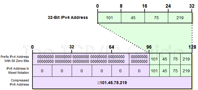
Since the IPv6 address space is so much bigger than that of IPv4, embedding the latter within the former is easy; it's like tucking a compact sedan into the hold of a cargo ship. The embedding address space is part of thereserved address block whose addresses begin with eight zero bits, but only a relatively small part of it. Two different embedding formats are used. Both have zeroes for the first 80 bits of the address, and put the embedded IPv4 address into the last 32 bits of the IPv6 address format. They differ on the value of the 16 remaining bits in between (bits 81 to 96, counting from the left):
The two embedding formats are used in order to indicate the capabilities of the device using the embedded address.

IPv4-Compatible IPv6 Addresses
These are special addresses assigned to IPv6-capable devices, such as so-called “dual stack” devices that speak both IPv4 and IPv6. They have all zeroes for the middle 16 bits; thus, they start off with a string of 96 zeroes, followed by the IPv4 address. An example of such an address, shown in Figure 1, would be 0:0:0:0:0:0:101.45.75.219 in mixed notation, or more succinctly, ::101.45.75.219.


Figure 1: IPv4-Compatible Embedded IPv6 Address Representation

IPv4-Mapped IPv6 Addresses
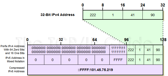
These are regular IPv4 addresses that have been mapped into the IPv6 address space, and are used for devices that are only IPv4-capable. They have a set of 16 ones after the initial string of 80 zeroes, and then the IPv4 address. So, if an IPv4 device has the address 222.1.41.90, such as the one in Figure 2, it would be represented as 0:0:0:0:0:FFFF:222.1.41.90, or ::FFFF:222.1.41.90.


Figure 2: IPv4-Mapped Embedded IPv6 Address Representation

Key Concept: IPv4 address embedding is used to create a relationship between an IPv4 address and an IPv6 address to aid in the transition from IPv4 to IPv6. One type, the IPv4-compatible IPv6 address, is used for devices that are compatible with both IPv4 and IPv6; it begins with 96 zero bits. The other, the IPv4-mapped address, is used for mapping IPv4 devices that are not compatible with IPv6 into the IPv6 address space; it begins with 80 zeroes followed by 16 ones.

Comparing IPv4-Compatible and IPv4-Mapped Embedded IPv6 Addresses
The difference between these two kinds of addresses is subtle, but important. The first 80 bits are always zero, so when this is seen you know it is an embedded IPv4 address of some sort. IPv4-compatible IPv6 addresses are only used for devices that are actually IPv6-aware; the IPv4-compatible address is in addition to its conventional IPv6 address. In contrast, if the "FFFF" is seen for the 16 bits after the initial 80, this designates a conventional IPv4 device whose IPv4 address has been mapped into the IPv6 format. It is not an IPv6-capable device.


::/128 - Unspecified
::1/128 - Loopback
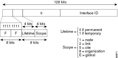
FF00::/8 - Multicast
FE80::/10 - Link-local unicast
FC00::/7 - Unique local unicast
2000::/3 - Global unicast

Global Unicast - like public IP address in IPv4


Multicast - same same, replacing the need of broadcast.


Anycast - finds the nearest IP


Unique local unicast address - like private address (RFC 1918)


Link local unicast address - direct connection without any router. Autoconfiguration of the address, can be few attached to the single interface, routers are not forwarding this IPs.


IPv6 Mechanisms
            ICMPv6
             
            IPv6Neighbor Discovery Protocol
            
            IPv6 Name Resolution
IPv4 uses A record to resolve IP per DNS name, DNS adds a resource record (RR) to support name-to-IPv6-address resolution. New type of record calls AAAA.

Path MTU Discovery
IPv6 does not allow packet segmentation thru the internetwork. Only sending host are allowed to fragment. Maximum MTU is 1280 per RFC 2460.

IPv6 Address-Assignment Strategies
Static or Dynamic:
            Static:
                        Manually
            Dynamic:
                        Stateless autoconfiguration of link-local address (FE80::)
                        Stateless autoconfiguration of globally unique address (
Statefull configuration with DHCPv6

            IPv6 Security
Extension headers carry the IPsec AH and ESP headers. The AH provides authentication and integrity. The ESP header provides confidentiality by encryption a payload.
                       

IPv6 Routing Protocols
            RIPng
            UDP port 521
            Uses multicast group FF02::9

EIGRP for IPv6
            Uses multicast group FF02::A

            OSPFv3
            Uses multicast group FF02::5 for all OSPF routers and FF02::6 for all DR’s.

            IS-IS for IPv6
            (draft)

            MP-BGP for IPv6
            MP_REACH_NLRI
            MP_UNREACH_NLRI
           

IPv4 to IPv6 Transition Mechanisms and Deployment Models

            TransitionMechanisms:
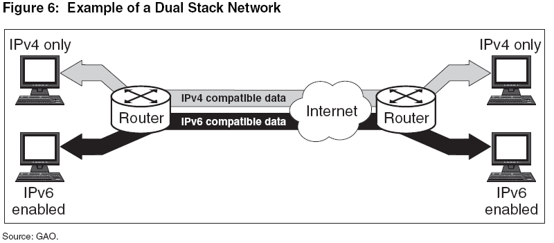
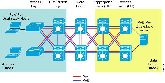
Dual-Stack (IPv4 and IPv6 coexist in host and network)


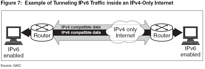
            Tunneling (IPv6 packets are encapsulated into IPv4 packets)
                        IPv4 compatible
                        6to4
                        6over4
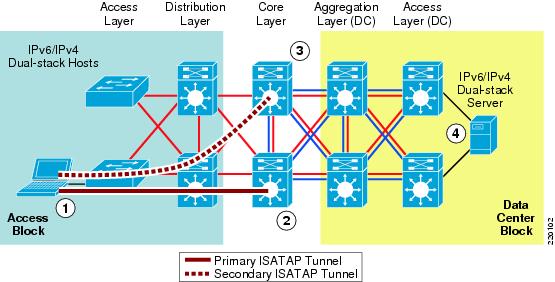
                        ISATAP


            Translation (IPv6 packets are translated to IPv6 packets)     
                        ALG
                        API
                        DSTM – NAT-PT


Summary:


            DeploymentModels:
            Dual-Stuck model


            Hybrid model


            Service Block Model


Summary:
IPv6 Deployment Model
Advantages
Disadvantages
Dual-Stack model
Tunneling not required. Better processing performance.
IPv4 & IPv6 independent routing, QoS, security and multicast policies.
Network equipment upgraded
Hybrid model 1
Existing network can be leveraged with no upgrades
IPv6 multicast not supported within ISATAP tunnel.
Terminating ISATAP tunnels in core makes the core appear to be in IPv6 access layer.
Hybrid model 2
IPv4 & IPv6 independent routing, QoS, security and multicast policies.
Many static tunnels which makes it difficult to manage.
Server Block model
Lesser impact on existing network.
Flexible when controlling access to IPv6-enabled applications.
Large amounts of tunneling.
Cost of additional equipment.


IPv6 Comparison with IPv4

Characteristics
IPv6
IPv4
Address length
128 bits
32 bits
Address representation
Hexadecimal
Dotted-decimal
Header length
Fixed (40 bytes)
Variable
Upper-layer protocol
Next header field
Protocol type field
Link address resolution
ND
ARP
Address configuration
Stateless autoconfiguration or Statefull DHCP
Statefull DHCP
Routing protocols
EIGRPv6, OSPFv6, RIPng, ISIS for IPv6
EIGRP, OSPFv2, RIPv2, ISIS
Classification and marking
Traffic Class and Flow label fields, DSCP
IP Precedence bits, ToS, DSCP
Private address
Unique-local address
RFC 1918
Fragmentation
Sending host only
Sending host and intermediate routers
Loopback address
0:0:0:0:0:0:0:1
127.0.0.1
Address scope type
Unicast, anycast, multicast
Unicast, multicast, broadcast