Wednesday, February 24, 2016

Data Center Microsegmentation

Data center microsegmentation can provide enhanced security for east-west traffic within the data center. 

Data centers historically have been protected by perimeter security technologies. These technologies include firewalls, intrusion detection and prevention platforms, and custom devices, all designed to aggressively analyze incoming traffic and help ensure that only authorized users can access data center resources. These services interdict and analyze north-south traffic: that is, traffic into and out of the data center. These services can be very effective at the perimeter, but they generally have not been provisioned to analyze device-to-device traffic within the data center, commonly referred to as east-west traffic. 


Historical Data Center Security Protection:

Modern application design, with the popularity of the N-tier web, application, and database application model, has vastly expanded the ratio of east-west traffic to north-south traffic. By some estimates, data centers may have five times as much east-west traffic as north-south traffic as dozens or hundreds of web, application, and database servers communicate to deliver services. 
Classic data center designs assume that all east-west traffic occurs in a well-protected trust zone. Any device inside the data center is generally authorized to communicate with any other device in the data center. Because all data center devices exist inside a hardened security perimeter, they should all be safe from outside incursion. Recent data breaches, however, have shown that such an assumption is not always valid. Whether through advanced social engineering or compromised third-party attacks, determined malefactors have shown the ability to penetrate one data center device and use that as a platform to launch further attacks inside the data center.


Microsegmentation and the New Data Center:

Microsegmentation divides the data center into smaller, more-protected zones. Instead of a single, hardened perimeter defense with free traffic flow inside the perimeter, a microsegmented data center has security services provisioned at the perimeter, between application tiers, and even between devices within tiers. The theory is that even if one device is compromised, the breach will be contained to a smaller fault domain. As a security design, microsegmentation makes sense. However, if such a data center relies on traditional firewall rules and manually maintained access control lists, it will quickly become unmanageable. An organization cannot simply create a list of prohibited traffic between nodes; that list will grow exponentially as attack vectors, vulnerabilities, and servers multiply.

The only workable solution is a trusted declarative (whitelist) security model in which security services specify the traffic that is permitted and everything else is denied. This solution requires tight integration between application and network services, and that integration is lacking in most data center deployments. Indeed, network analysis frequently demonstrates that applications are using unexpected traffic flows to deliver services, demonstrating the traditional disconnection between application, server, and network managers.


Application-Centric Networking:

Applications provide critical access to company data and reporting metrics associated with business outcomes. Essentially, delivery of secure applications is the most important task of the data center, so it necessarily follows that networking and infrastructure must be application-centric. The terms and constructs of applications must determine the flow, permissions, and services that the network delivers. The application profile must be able to tell the network how to deliver the required services.

This approach is what is known as a declarative model, which is an instantiation of promise theory. Devices are told what services to provision, and they promise to do it or to tell the control system what they can do. The application profile specifies the policy that must be provisioned. The network administrator declares that intended policy to the network devices, which then configure themselves to deliver the services (filtering, inspection, load balancing, quality of service [QoS], etc.) that are necessary for that application. This approach provides the best way to manage applications and network devices at scale.

The declarative model contrasts sharply with the traditional imperative model. In the imperative model, operators manually configure each network and Layer 4 through 7 device, specifying such parameters as VLANs, IP addresses, and TCP and User Datagram Protocol (UDP) ports. Even with scripting and third-party management tools, this process is a time-consuming and complicated endeavor. Moreover, configurations (such as firewall rules and access control lists [ACLs]) are often left unchanged as the network load changes, because altering a series of manually maintained ACLs can have unanticipated consequences. This approach leads to longer and longer firewall rule sets, longer and more complicated processing, and increased device load. As data centers have grown from tens to hundreds to thousands of devices, the imperative model is no longer sufficient.

With the declarative model, the responsibility for interpreting policy falls to the network, and the responsibility for programming devices falls to the devices themselves. This model has some important advantages over the imperative model:
● Scalability: Network management capability scales linearly with the network device count.
● Intelligence: The network maintains a logical view of all devices, endpoints, applications, and policy and intelligently specifies the subset of that view that each device needs to maintain.
● Holistic view of the data center: Services can truly be made available on demand and provisioned more efficiently, and unused services can be retired.


It’s About Policy:

An application-centric view of the infrastructure allows applications to request services from the network, and it provides the network intelligence to efficiently deliver those services. Security, whether macrosegmented or microsegmented, is just another service.

Security must be part of the overall data center policy. It must be considered and provisioned as an integral part of the services that the data center provides; it cannot stand alone. Security is usually provisioned as one of a series of services to be applied in a chain. Any modern data center must provide security and segmentation as one of the many services that are provisioned as dictated by the overall policy and compliance objectives.

Microsegmentation may require hundreds or thousands of security policy rules. It would be very difficult to provision all those rules manually. A declarative model enables the scale required, because the administrator only needs to pass the security and services policies to the network, which would then interprets and provisions the physical and virtual devices as needed. The administrator defines these policies within the logical model, which is an abstracted view of the network and everything connected to it. One important advantage of this logical model is that every device and service is an object, and logical objects can be created, replicated, modified, and applied as needed. One security and service policy can be applied a hundred times, or a hundred different, custom policies can be applied. This flexibility and exceptional level of control is inherent in the abstraction of the physical network into the logical model.

Requirements for the Modern Data Center

To deliver this policy effectively, the data center infrastructure must also support:

● Virtual servers, with flexible placement and workload mobility: Virtual machine managers and the network must communicate with each other, enabling rapid machine and service creation and virtual switch configuration for network policy.

● Physical servers, with flexible placement and mobility: Physical bare-metal servers are and will continue to be widely deployed and used. They must not be treated like less important elements by the data center infrastructure. They must have access to the same policies, services, and performance as virtual servers.

● Hypervisors from a number of vendors as well as open-source hypervisors: Most data centers do not rely on a single hypervisor, and an infrastructure that effectively supports only one hypervisor drastically restricts performance and service flexibility.

● Open northbound interfaces to orchestration platforms and development and operations (DevOps) tools, such as OpenStack and Puppet and Chef: Network automation goes well beyond virtual machine management, and the infrastructure needs to support a wide range of automation platforms.

● Open southbound protocols to a broad ecosystem of physical and virtual devices: Security and other services are provided by a number of vendors, and the modern data center infrastructure must support those devices in the same declarative manner that it supports routers and switches.

● Services at line rate, whether 1, 10, or 40 Gbps or beyond: Today’s data center traffic patterns rely on consistently low latency, high speed, and efficient fabric utilization, and any infrastructure that doesn’t provide all three should not be considered. All three characteristics must be available to all devices and services, without gateway devices or other latency-inducing extra hops.

● Tight logical-physical integration for provisioning and troubleshooting: The network control system cannot just tell the network devices how to configure themselves; there must be full, two-way communication. This tight integration provides a real-time view of network utilization, latency, and other parameters, enabling the control system to more effectively deploy needed services and troubleshoot any problems that may occur. Without this integration, provisioning is performed without any insight, and troubleshooting requires examining two distinct network structures: a virtual one and a physical one.

Cisco Application Centric Infrastructure

Cisco® Application Centric Infrastructure (ACI) provides true microsegmentation in an effective manner. Cisco ACI abstracts the network, devices, and services into a hierarchical, logical object model. In this model, administrators specify the services (firewalls, load balancers, etc.) that are applied, the kind of traffic they are applied to, and the traffic that is permitted. These services can be chained together and are presented to application developers as a single object with a simple input and output. Connection of application-tier objects and server objects creates an application network profile (ANP). When this ANP is applied to the network, the devices are told to configure themselves to support it. Tier objects can be groups of hundreds of servers, or just one; all are treated with the same policies in a single configuration step.

Cisco ACI provides this scalability and flexibility to both physical servers and virtual machines, and it provides virtual machine management to several market-leading hypervisors. If permitted by the network policy, vendor A’s virtual machine can speak freely to vendor B’s virtual machine as if they were in the same hypervisor.

Cisco ACI exposes a published northbound Representational State Transfer (REST) API through XML and JavaScript Object Notation (JSON), as well as a Python software development kit (SDK), allowing easy integration with popular tools such as Cisco UCS® Director, OpenStack, and Puppet and Chef. The system also provides an open source southbound API, which allows third-party network service vendors to implement policy control.

The Cisco ACI fabric is built on Cisco Nexus® 9000 Series switches, the fastest and greenest 40-Gbps switches on the market today. A Cisco ACI fabric is deployed in a spine-and-leaf architecture and supports advanced equal-cost multipath (ECMP) routing, enabling 40 percent greater network efficiency than conventional architecture. Every end device, whether physical or virtual, connects to a leaf port, and every device’s traffic is switched at line rate through the fabric. There are no gateway devices to add latency or interfere with policy application.

The fabric is abstracted by the logical model, not virtualized. Therefore, the network control systems have full visibility into the physical domain as well as the virtual domain. For example, Cisco ACI maintains a real-time measure of latency through every path in the network, which other networking solutions can’t do. The system maintains health scores for all devices, applications, and tenants, quickly flagging any degraded condition and programmatically reconfiguring the network as needed.

Conclusion

Microsegmentation provides internal control of traffic within the data center and can greatly enhance a data center’s security posture. Cisco ACI is the only solution available today that enables true microsegmentation with the performance, scalability, and visibility that modern applications demand.
Monday, February 22, 2016

QUIC

QUIC (Quick UDP Internet Connections, pronounced quick) is an experimental transport layer network protocol designed by Jim Roskind at Google, initially implemented in 2012, and announced as experimentation broadened in 2013. QUIC supports a set of multiplexed connections between two endpoints over User Datagram Protocol (UDP), and was designed to provide security protection equivalent to TLS/SSL, along with reduced connection and transport latency, and bandwidth estimation in each direction to avoid congestion
QUIC's main goal is to improve perceived performance of connection-oriented web applications that are currently using TCP. It also provides a venue for rapid iteration of congestion avoidance algorithms, placing control into application space at both endpoints, rather than (the relatively slow to evolve) kernel space.

UDP’s (and QUIC’s) counterpart in the protocol world is basically TCP (which in combination with the Internet Protocol (IP) makes up the core communication language of the Internet). UDP is significantly more lightweight than TCP, but in return, it features far fewer error correction services than TCP. This means that the sending server isn’t constantly talking to the receiving server to check if packages arrived and if they arrived in the right order, for example. That’s why UDP is great for gaming services. For these services, you want low overhead to reduce latency and if the server didn’t receive your latest mouse movement, there’s no need to spend a second or two to fix that because the action has already moved on. You wouldn’t want to use it to request a website, though, because you couldn’t guarantee that all the data would make it.

http://techcrunch.com/2015/04/18/google-wants-to-speed-up-the-web-with-its-quic-protocol/

With QUIC, Google aims to combine some of the best features of UDP and TCP with modern security tools.

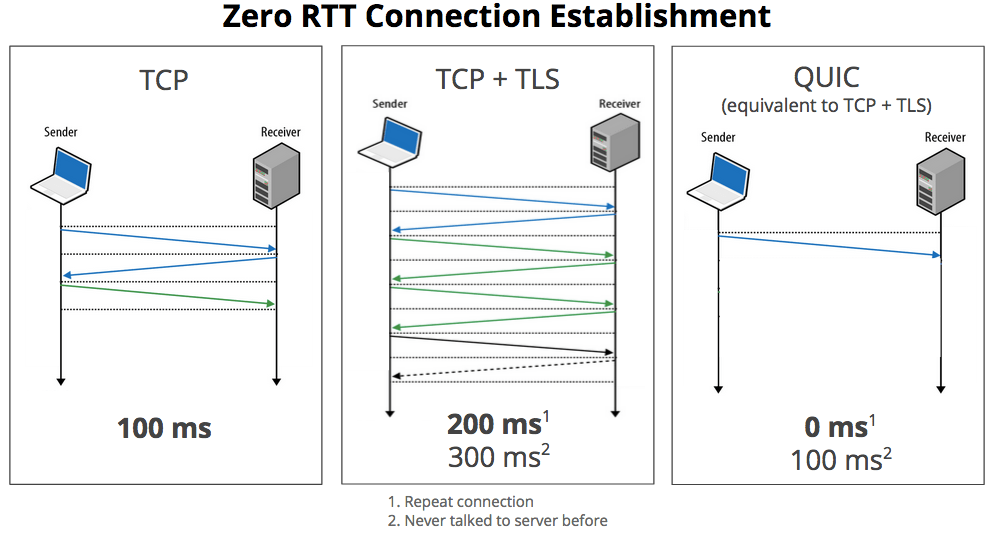
On a typical secure TCP connection, it typically takes two or three round-trips before the browser can actually start receiving data. Using QUIC, a browser can immediately start talking to a server it has talked to before. QUIC also introduces a couple of new features like congestion control and automatic re-transmission, making it more reliable that pure UDP.
With SPDY, which later became the basis for the HTTP/2 standard, Google already developed another alternative protocol that had many of the same goals as QUIC, but HTTP/2 still runs over TCP and still runs into some of the same latency cost.

QUIC Geek FAQ (for folks that know about UDP, TCP, SPDY, and stuff like that)


What is QUIC?  QUIC is the name for a new experimental protocol, and it stands for Quick UDP Internet Connection.  The protocol supports a set multiplexed connections over UDP, and was designed to provide security protection equivalent to TLS/SSL, along with reduced connection and transport latency. An experimental implementation is being put in place in Chrome by a team of engineers at Google.

What are some of the distinctive techniques being tested in QUIC?  QUIC will employ bandwidth estimation in each direction into congestion avoidance, and then pace packet transmissions evenly to reduce packet loss.  It will also use packet-level error correction codes to reduce the need to retransmit lost packet data.  QUIC aligns cryptographic block boundaries with packet boundaries, so that packet loss impact is further contained.

Doesn’t SPDY already provide multiplexed connections over SSL?  Yes, but SPDY currently runs across TCP, and that induces some undesirable latency costs (even though SPDY is already producing lower latency results than traditional HTTP over TCP).

Why isn’t SPDY over TCP good enough?  A single lost packet in an underlying TCP connection stalls all of the multiplexed SPDY streams over that connection. By comparison, a single lost packet for X parallel HTTP connections will only stall 1 out of X connections. With UDP, QUIC can support out-of-order delivery, so that a lost packet will typically impact (stall) at most one stream. TCP’s congestion avoidance via a single congestion window also puts SPDY at a disadvantage over TCP when compared to several HTTP connections, each with a separate congestion window. Separate congestion windows are not impacted as much by a packet loss, and we hope that QUIC will be able to more equitably handle congestion for a set of multiplexed connections.

Are there any other reasons why TCP isn’t good enough?  TCP, and TLS/SSL, routinely require one or more round trip times (RTTs) during connection establishment.  We’re hopeful that QUIC can commonly reduce connection costs towards zero RTTs. (i.e., send hello, and then send data request without waiting).

Why can’t you just evolve and improve TCP under SPDY?  That is our goal. TCP support is built into the kernel of operating systems. Considering how slowly users around the world upgrade their OS, it is unlikely to see significant adoption of client-side TCP changes in less than 5-15 years. QUIC allows us to test and experiment with new ideas, and to get results sooner. We are hopeful that QUIC features will migrate into TCP and TLS if they prove effective.

Why didn’t you build a whole new protocol, rather than using UDP? Middle boxes on the Internet today will generally block traffic unless it is TCP or UDP traffic.  Since we couldn’t significantly modify TCP, we had to use UDP.  UDP is used today by many game systems, as well as VOIP and streaming video, so its use seems plausible.

Why does QUIC always require encryption of the entire channel?  As we learned with SPDY and other protocols, if we don’t encrypt the traffic, then middle boxes are guaranteed to (wittingly, or unwittingly) corrupt the transmissions when they try to “helpfully” filter or “improve” the traffic.

UDP doesn’t have congestion control, so won’t QUIC cause Internet collapse if widely adopted?  QUIC employs congestion controls, just as it employs automatic retransmission to support reliable transport.  QUIC will attempt to be fair with competing TCP traffic.  For instance, when conveying Q multiplexed flows, and sharing bandwidth with T concurrent TCP flows, we will try to use resources in the range of Q / (Q+T) bandwidth (i.e., “a fair share” for Q additional flows).

Why didn’t you use existing standards such as SCTP over DTLS?  QUIC incorporates many techniques in an effort to reduce latency. SCTP and DTLS were not designed to minimize latency, and this is significantly apparent even during the connection establishment phases. Several of the techniques that QUIC is experimenting with would be difficult technically to incorporate into existing standards. As an example, each of these other protocols require several round trips to establish a connection, which is at odds with our target of 0-RTT connectivity overhead.

How much do QUIC’s techniques reduce latency? This is exactly the question we are investigating at the moment, and why we are experimenting with various features and techniques in Chromium. It is too early to share any preliminary results - stay tuned.

Is there any way to disable QUIC, if I really want to avoid running it on my Chromium browser?  Yes.  You can visit about:flags and set the “Experimental QUIC protocol” to “Disabled.”

Where can I learn more about QUIC?  If you want a lot of background, and need material to help you sleep, you can look at the QUIC Design Document and Specification Rationale.  For cryptographers that wonder how well the i’s are dotted, and t’s crossed, there is a QUIC Crypto Specification.  If you’d rather see client code, you can take a look at the Chromium source directory.  If you’re wondering about what a server might have to do, there is some prototype server code.  Finally, if you just want to think about the bits on the wire, and how this might look, there is an evolving wire specification.

Is there a news group for discussing QUIC?  Yes.  proto-quic@chromium.org a.k.a., https://groups.google.com/a/chromium.org/d/forum/proto-quic


Phonetic Alphabet...Always needed....


Understand Secure Sockets Layer (SSL)

Understanding SSL

Regardless of where you access the Internet from, the connection between your Web browser and any other point can be routed through dozens of independent systems. Through snooping, spoofing, and other forms of Internet eavesdropping, unauthorized people can steal credit card numbers, PIN numbers, personal data, and other confidential information.

The Secure Sockets Layer (SSL) protocol was developed to transfer information privately and securely across the Internet. SSL is layered beneath application protocols such as HTTP, SMTP, and FTP and above the connection protocol TCP/IP. It is used by the HTTPS access method. Figure 1 illustrates the difference between a non-secure HTTP request and a secure SSL request.
Transport Layer Security (TLS) is the successor of Secure Sockets Layer (SSL); they are both cryptographic protocols that provide secure communications on the Internet for such things as web browsing, e-mail, Internet faxing, instant messaging, and other data transfers. There are slight differences between SSL and TLS, but the protocol remains substantially the same.


How It Works

When a client and server communicate, SSL ensures that the connection is private and secure by providing authentication, encryption, and integrity checks. Authentication confirms that the server, and optionally the client, is who they say they are. Encryption through a key-exchange then creates a secure “tunnel” between the two that prevents any unauthorized system from reading the data. Integrity checks guarantee that any unauthorized system cannot modify the encrypted stream without
being detected. 

SSL-enabled clients (such as a Mozilla™ or Microsoft Internet Explorer™ web browser) and SSL-enabled servers (such as Apache or Microsoft IIS™) confirm each other’s identities using digital certificates. Digital certificates are issued by trusted third parties called Certificate Authorities (CAs) and provide information about an individual’s claimed identity, as well as their public key. Public keys are a component of public-key cryptographic systems. The sender of a message uses a public key to encrypt data. The recipient of the message can only decrypt the data with the corresponding private key. Public keys are known to everybody; private keys are secret and only known to the owner of the certificate. By validating the CA digital signature on the certificates, both parties can ensure that an imposter has not intercepted the transmission and provided a false public key for which they have the correct private key. SSL uses both public-key and symmetric key encryption. Symmetric key encryption is much faster than public-key encryption, but public-key encryption provides better authentication techniques. So SSL uses public key cryptography for authentication and for exchanging the symmetric keys that are used later for bulk data encryption.

The secure tunnel that SSL creates is an encrypted connection that ensures that all information sent between an SSL-enabled client and an SSL-enabled server remains private. SSL also provides a mechanism for detecting if someone has altered the data in transit. This is done with the help of message integrity checks. These message integrity checks ensure that the connection is reliable. If, at any point during a transmission, SSL detects that a connection is not secure, it terminates the connection and the client and server establish a new secure connection.

SSL Transactions

The SSL transaction has two phases: the SSL Handshake (the key exchange) and the SSL data transfer. These phases work together to secure an SSL transaction.


Figure 2 illustrates an SSL transaction:
1. The handshake begins when a client connects to an SSL-enabled server, requests a secure connection, and presents a list of supported ciphers and versions.
2. From this list, the server picks the strongest cipher and hash function that it also supports and notifies the client of the decision. Additionally, the server sends back its identification in the form of a digital certificate. The certificate usually contains the server name, the trusted certificate authority (CA), and the server’s public encryption key. The server may require client authentication via a signed certificate as well (required for some on-line banking operations); however, many organizations choose not to widely deploy client-side certificates due to the overhead involved in managing a public key infrastructure (PKI).
3. The client verifies that the certificate is valid and that a Certificate Authority (CA) listed in the client’s list of trusted CAs issued it. These CA certificates are typically locally configured.
4. If it determines that the certificate is valid, the client generates a master secret, encrypts it with the server’s public key, and sends the result to the server. When the server receives the master secret, it decrypts it with its private key. Only the server can decrypt it using its private key.
5. The client and server then convert the master secret to a set of symmetric keys called a keyring or the session keys. These symmetric keys are common keys that the server and browser can use to encrypt and decrypt data. This is the one fact that makes the keys hidden from third parties, since only the server and the client have access to the private keys.
6. This concludes the handshake and begins the secured connection allowing the bulk data transfer, which is encrypted and decrypted with the keys until the connection closes. If any one of the above steps fails, the SSL handshake fails, and the connection is not created.

Though the authentication and encryption process may seem rather involved, it happens in less than a second. Generally, the user does not even know it is taking place. However, the user is able to tell when the secure tunnel has been established since most SSL-enabled web browsers display a small closed lock at the bottom (or top) of their screen when the connection is secure. Users can also identify secure web sites by looking at the web site address; a secure web site’s address begins with https rather than the usual http.

SSL Crypto Algorithms

SSL supports a variety of different cryptographic algorithms, or ciphers, that it uses for authentication, transmission of certificates, and establishing session keys. SSL-enabled devices can be configured to support different sets of ciphers, called cipher suites. If an SSL-enabled client and an SSL-enabled server support multiple cipher suites, the client and server negotiate which cipher suites they use to provide the strongest possible security supported by both parties.
A ciphersuite specifies and controls the various cryptographic algorithms used during the SSL handshake and the data transfer phases. Specifically, a cipher suite provides the following:
--> Key exchange algorithm: The asymmetric key algorithm used to exchange the symmetric key. RSA and Diffie Hellman are common examples.
--> Public key algorithm: The asymmetric key algorithm used for authentication. This decides the type of certificates used. RSA and DSA are common examples.
--> Bulk encryption algorithm: The symmetric algorithm used for encrypting data. RC4, AES, and Triple-DES are common examples.
--> Message digest algorithm: The algorithm used to perform integrity checks. MD5 and SHA-1 are common examples.
For instance the cipher suite “RSA-RC4-MD5” means that RSA certificates are used for both authentication and key exchange, while RC4 is used as the bulk encryption cipher, and MD5 is used for digest computation.

SSL and the OSI Model

The SSL protocol is a security protocol that sits on top of TCP at the transport layer. In the OSI model, application layer protocols such as HTTP or IMAP, handle user application tasks such as displaying web pages or running email servers.
Session layer protocols establish and maintain communications channels. Transport layer protocols such as TCP and UDP, handle the flow of data between two hosts. Network layer protocols such as IP and ICMP provide hop-by-hop handling of data packets across the network.
SSL operates independently and transparently of other protocols so it works with any application layer and any transport layer protocol. This allows clients and servers to establish secure SSL connections without requiring knowledge of the other party’s code.

Figure 3 illustrates how SSL functions in the OSI model:
An application layer protocol hands unencrypted data to the session/transport layer, SSL encrypts the data and hands it down through the layers. When the server receives the data at the other end, it passes it up through the layers to the session layer where SSL decrypts it and hands it off to the application layer. Since the client and the server have gone through the key negotiation handshake, the symmetric key used by SSL is the same at both ends.

Cisco Catalyst Multigigabit Ethernet

Q. What is Cisco Multigigabit Ethernet?
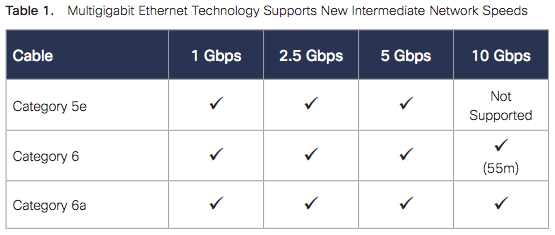
A. Cisco® Multigigabit Ethernet is a unique Cisco innovation to the new Cisco Catalyst® Ethernet Access Switches. With the enormous growth of 802.11ac and new wireless applications, wireless devices are driving the demand for more network bandwidth. This creates a need for a technology that supports speeds higher than 1 Gbps on all cabling infrastructure. Cisco multigigabit technology allows you to achieve bandwidth between speeds of 1 and 10 Gbps over traditional Cat 5e cabling or above. In addition, the multigigabit ports on select Cisco Catalyst switches support Universal Power Over Ethernet (UPOE), which is increasingly important for next-generation workspaces and Internet of Things (IoT) ecosystems.

Q. What are the key benefits of this new technology?
A. Cisco multigigabit technology offers significant benefits for a diverse range of speeds, cable types, and Power Over Ethernet (POE) power. The benefits can be grouped into three different areas:
● Multiple speeds: Cisco multigigabit technology supports auto-negotiation of multiple speeds on switch ports. The supported speeds are 100 Mbps, 1 Gbps, 2.5 Gbps, and 5 Gbps on Cat 5e cable and up to 10 Gbps over Cat 6a cabling.
● Cable type: The technology supports a wide range of cable types including Cat 5e, Cat 6, and Cat 6a or above.
● POE power: The technology supports POE, POE+, and UPOE for all the supported speeds and cable types.


http://www.cisco.com/c/dam/en/us/solutions/collateral/enterprise-networks/catalyst-multigigabit-switching/multigigabit-ethernet-technology.pdf

Ericsson Teams Up With Amazon Web Services

Ericsson is enlisting the help of Amazon Web Services (AWS) to help bring telecom providers into the brave new world of cloud-based services.
The partnership was among a horde of announcements put forth by Ericsson today at Mobile World Congress in Barcelona (not to mention the swarm that came before MWC). It’s less about telcos competing with AWS and more about them coming to AWS, looking to exploit cloud infrastructure just as enterprises have started doing.

Monday, March 19, 2012

CCDA Done!!! Certified on Friday. :)

CCDA Done!!! Certified on Friday. :)
Now moving to CCDP.... 
Only one exam needed for CCNP certified professional to get CCDP certificate.

ARCH 642-874

Only one book for preparations from Cisco Press:
Designing Cisco Network Service Architectures (ARCH) Foundation Learning Guide: (CCDP ARCH 642-874) (3rd Edition) (Foundation Learning Guides)

Will start from it...

Wednesday, January 25, 2012

CCDA 640-864 Official Cert Guide - Chapter 15 Summary


Simple Network Management Protocol
Overview and basic concepts
In typical SNMP uses, one or more administrative computers, called managers, have the task of monitoring or managing a group of hosts or devices on a computer network. Each managed system executes, at all times, a software component called an agent which reports information via SNMP to the manager.
Essentially, SNMP agents expose management data on the managed systems as variables. The protocol also permits active management tasks, such as modifying and applying a new configuration through remote modification of these variables. The variables accessible via SNMP are organized in hierarchies. These hierarchies, and other metadata (such as type and description of the variable), are described by Management Information Bases (MIBs).

An SNMP-managed network consists of three key components:
Managed device
Agent — software which runs on managed devices
Network management system (NMS) — software which runs on the manager
A managed device is a network node that implements an SNMP interface that allows unidirectional (read-only) or bidirectional access to node-specific information. Managed devices exchange node-specific information with the NMSs. Sometimes called network elements, the managed devices can be any type of device, including, but not limited to, routers, access servers, switches, bridges, hubs, IP telephones, IP video cameras, computer hosts, and printers.
An agent is a network-management software module that resides on a managed device. An agent has local knowledge of management information and translates that information to or from an SNMP specific form.
A network management system (NMS) executes applications that monitor and control managed devices. NMSs provide the bulk of the processing and memory resources required for network management. One or more NMSs may exist on any managed network.

Management information base (MIB)
Main article: Management information base
SNMP itself does not define which information (which variables) a managed system should offer. Rather, SNMP uses an extensible design, where the available information is defined by management information bases (MIBs). MIBs describe the structure of the management data of a device subsystem; they use a hierarchical namespace containing object identifiers (OID). Each OID identifies a variable that can be read or set via SNMP. MIBs use the notation defined by ASN.1.

Protocol details

SNMP operates in the Application Layer of the Internet Protocol Suite (Layer 7 of the OSI model). The SNMP agent receives requests on UDP port 161. The manager may send requests from any available source port to port 161 in the agent. The agent response will be sent back to the source port on the manager. The manager receives notifications (Traps and InformRequests) on port 162. The agent may generate notifications from any available port. When used with Transport Layer Security or Datagram Transport Layer Security requests are received on port 10161 and traps are sent to port 10162.
SNMPv1 specifies five core protocol data units (PDUs). Two other PDUs, GetBulkRequest and InformRequest were added in SNMPv2 and carried over to SNMPv3.

All SNMP PDUs are constructed as follows:
IP header         UDP header    version community      PDU-type        request-id        error-status      error-index            variable bindings

The seven SNMP protocol data units (PDUs) are as follows:
GetRequest
A manager-to-agent request to retrieve the value of a variable or list of variables. Desired variables are specified in variable bindings (values are not used). Retrieval of the specified variable values is to be done as an atomic operation by the agent. A Response with current values is returned.
SetRequest
A manager-to-agent request to change the value of a variable or list of variables. Variable bindings are specified in the body of the request. Changes to all specified variables are to be made as an atomic operation by the agent. A Response with (current) new values for the variables is returned.
GetNextRequest
A manager-to-agent request to discover available variables and their values. Returns a Response with variable binding for the lexicographically next variable in the MIB. The entire MIB of an agent can be walked by iterative application of GetNextRequest starting at OID 0. Rows of a table can be read by specifying column OIDs in the variable bindings of the request.
GetBulkRequest
Optimized version of GetNextRequest. A manager-to-agent request for multiple iterations of GetNextRequest. Returns a Response with multiple variable bindings walked from the variable binding or bindings in the request. PDU specific non-repeaters and max-repetitions fields are used to control response behavior. GetBulkRequest was introduced in SNMPv2.
Response
Returns variable bindings and acknowledgement from agent to manager for GetRequest, SetRequest, GetNextRequest, GetBulkRequest and InformRequest. Error reporting is provided by error-status and error-index fields. Although it was used as a response to both gets and sets, this PDU was called GetResponse in SNMPv1.
Trap
Asynchronous notification from agent to manager. Includes current sysUpTime value, an OID identifying the type of trap and optional variable bindings. Destination addressing for traps is determined in an application-specific manner typically through trap configuration variables in the MIB. The format of the trap message was changed in SNMPv2 and the PDU was renamed SNMPv2-Trap.
InformRequest
Acknowledged asynchronous notification manager to manager or agent to manager. Manager-to-manager notifications were already possible in SNMPv1 (using a Trap), but as SNMP commonly runs over UDP where delivery is not assured and dropped packets are not reported, delivery of a Trap was not guaranteed. InformRequest fixes this by sending back an acknowledgement on receipt. Receiver replies with Response parroting all information in the InformRequest. This PDU was introduced in SNMPv2.

Version 1
SNMP version 1 (SNMPv1) is the initial implementation of the SNMP protocol. SNMPv1 operates over protocols such as User Datagram Protocol (UDP), Internet Protocol (IP), OSI Connectionless Network Service (CLNS), AppleTalk Datagram-Delivery Protocol (DDP), and Novell Internet Packet Exchange (IPX). SNMPv1 is widely used and is the de facto network-management protocol in the Internet community.
The first RFCs for SNMP, now known as SNMPv1, appeared in 1988:
RFC 1065 — Structure and identification of management information for TCP/IP-based internets
RFC 1066 — Management information base for network management of TCP/IP-based internets
RFC 1067 — A simple network management protocol
These protocols were obsoleted by:
RFC 1155 — Structure and identification of management information for TCP/IP-based internets
RFC 1156 — Management information base for network management of TCP/IP-based internets
RFC 1157 — A simple network management protocol
After a short time, RFC 1156 (MIB-1) was replaced by more often used:
RFC 1213 — Version 2 of management information base (MIB-2) for network management of TCP/IP-based internets
Version 1 has been criticized for its poor security. Authentication of clients is performed only by a "community string", in effect a type of password, which is transmitted in cleartext. The '80s design of SNMP V1 was done by a group of collaborators who viewed the officially sponsored OSI/IETF/NSF (National Science Foundation) effort (HEMS/CMIS/CMIP) as both unimplementable in the computing platforms of the time as well as potentially unworkable. SNMP was approved based on a belief that it was an interim protocol needed for taking steps towards large scale deployment of the Internet and its commercialization. In that time period Internet-standard authentication/security was both a dream and discouraged by focused protocol design groups.

Version 2
SNMPv2 (RFC 1441–RFC 1452), revises version 1 and includes improvements in the areas of performance, security, confidentiality, and manager-to-manager communications. It introduced GetBulkRequest, an alternative to iterative GetNextRequests for retrieving large amounts of management data in a single request. However, the new party-based security system in SNMPv2, viewed by many as overly complex, was not widely accepted.
Community-Based Simple Network Management Protocol version 2, or SNMPv2c, is defined in RFC 1901–RFC 1908. In its initial stages, this was also informally known as SNMPv1.5. SNMPv2c comprises SNMPv2 without the controversial new SNMP v2 security model, using instead the simple community-based security scheme of SNMPv1. While officially only a "Draft Standard", this is widely considered the de facto SNMPv2 standard.
User-Based Simple Network Management Protocol version 2, or SNMPv2u, is defined in RFC 1909–RFC 1910. This is a compromise that attempts to offer greater security than SNMPv1, but without incurring the high complexity of SNMPv2. A variant of this was commercialized as SNMP v2*, and the mechanism was eventually adopted as one of two security frameworks in SNMP v3.

SNMPv1 & SNMPv2c interoperability
As presently specified, SNMPv2 is incompatible with SNMPv1 in two key areas: message formats and protocol operations. SNMPv2c messages use different header and protocol data unit (PDU) formats from SNMPv1 messages. SNMPv2c also uses two protocol operations that are not specified in SNMPv1. Furthermore, RFC 2576 defines two possible SNMPv1/v2c coexistence strategies: proxy agents and bilingual network-management systems.

Proxy agents
A SNMPv2 agent can act as a proxy agent on behalf of SNMPv1 managed devices, as follows:
A SNMPv2 NMS issues a command intended for a SNMPv1 agent.
The NMS sends the SNMP message to the SNMPv2 proxy agent.
The proxy agent forwards Get, GetNext, and Set messages to the SNMPv1 agent unchanged.
GetBulk messages are converted by the proxy agent to GetNext messages and then are forwarded to the SNMPv1 agent.
The proxy agent maps SNMPv1 trap messages to SNMPv2 trap messages and then forwards them to the NMS.

Bilingual network-management system
Bilingual SNMPv2 network-management systems support both SNMPv1 and SNMPv2. To support this dual-management environment, a management application in the bilingual NMS must contact an agent. The NMS then examines information stored in a local database to determine whether the agent supports SNMPv1 or SNMPv2. Based on the information in the database, the NMS communicates with the agent using the appropriate version of SNMP.

Version 3
Although SNMPv3 makes no changes to the protocol aside from the addition of cryptographic security, its developers have managed to make things look much different by introducing new textual conventions, concepts, and terminology.
SNMPv3 primarily added security and remote configuration enhancements to SNMP.
Security has been the biggest weakness of SNMP since the beginning. Authentication in SNMP Versions 1 and 2 amounts to nothing more than a password (community string) sent in clear text between a manager and agent. Each SNMPv3 message contains security parameters which are encoded as an octet string. The meaning of these security parameters depends on the security model being used.

SNMPv3 provides important security features:
Confidentiality - Encryption of packets to prevent snooping by an unauthorized source.
Integrity - Message integrity to ensure that a packet has not been tampered with in transit including an optional packet replay protection mechanism.
Authentication - to verify that the message is from a valid source.
As of 2004 the IETF recognizes Simple Network Management Protocol version 3 as defined by RFC 3411–RFC 3418 (also known as STD0062) as the current standard version of SNMP. The IETF has designated SNMPv3 a full Internet standard, the highest maturity level for an RFC. It considers earlier versions to be obsolete (designating them "Historic").
In practice, SNMP implementations often support multiple versions: typically SNMPv1, SNMPv2c, and SNMPv3.

RMON

An RMON implementation typically operates in a client/server model. Monitoring devices (commonly called "probes" in this context) contain RMON software agents that collect information and analyze packets. These probes act as servers and the Network Management applications that communicate with them act as clients. While both agent configuration and data collection use SNMP, RMON is designed to operate differently than other SNMP-based systems:
Probes have more responsibility for data collection and processing, which reduces SNMP traffic and the processing load of the clients.
Information is only transmitted to the management application when required, instead of continuous polling.
In short, RMON is designed for "flow-based" monitoring, while SNMP is often used for "device-based" management. RMON is similar to other flow-based monitoring technologies such as NetFlow and SFlow because the data collected deals mainly with traffic patterns rather than the status of individual devices. One disadvantage of this system is that remote devices shoulder more of the management burden, and require more resources to do so. Some devices balance this trade-off by implementing only a subset of the RMON MIB groups (see below). A minimal RMON agent implementation could support only statistics, history, alarm, and event.

The RMON1 MIB consists of ten groups:
  • Statistics: real-time LAN statistics e.g. utilization, collisions, CRC errors
  • History: history of selected statistics
  • Alarm: definitions for RMON SNMP traps to be sent when statistics exceed defined thresholds
  • Hosts: host specific LAN statistics e.g. bytes sent/received, frames sent/received
  • Hosts top N: record of N most active connections over a given time period
  • Matrix: the sent-received traffic matrix between systems
  • Filter: defines packet data patterns of interest e.g. MAC address or TCP port
  • Capture: collect and forward packets matching the Filter
  • Event: send alerts (SNMP traps) for the Alarm group

The RMON2 MIB adds ten more groups:
  • Protocol Directory: list of protocols the probe can monitor
  • Protocol Distribution: traffic statistics for each protocol
  • Address Map: maps network-layer (IP) to MAC-layer addresses
  • Network-Layer Host: layer 3 traffic statistics, per each host
  • Network-Layer Matrix: layer 3 traffic statistics, per source/destination pairs of hosts
  • Application-Layer Host: traffic statistics by application protocol, per host
  • Application-Layer Matrix: traffic statistics by application protocol, per source/destination pairs of hosts
  • User History: periodic samples of user-specified variables
  • Probe Configuration: remote configure of probes
  • RMON Conformance: requirements for RMON2 MIB conformance


NetFlow

NetFlow is a network protocol developed by Cisco Systems for collecting IP traffic information. NetFlow has become an industry standard for traffic monitoring and is supported by platforms other than Cisco IOS and NXOS such as Juniper routers, Enterasys Switches, vNetworking in version 5 of vSphere, Linux, FreeBSD, NetBSD and OpenBSD.

Network Flows
Main article: Packet flow
A network flow has been defined in many ways. The traditional Cisco definition is to use a 7-tuple key, where a flow is defined as a unidirectional sequence of packets all sharing all of the following 7 values:
  • Source IP address
  • Destination IP address
  • Source port for UDP or TCP, 0 for other protocols
  • Destination port for UDP or TCP, type and code for ICMP, or 0 for other protocols
  • IP protocol
  • Ingress interface (SNMP ifIndex)
  • IP Type of Service
  
CDP

The Cisco Discovery Protocol (CDP) is a proprietary Data Link Layer network protocol developed by Cisco Systems. It is used to share information about other directly connected Cisco equipment, such as the operating system version and IP address. CDP can also be used for On-Demand Routing, which is a method of including routing information in CDP announcements so that dynamic routing protocols do not need to be used in simple network.

Syslog

Syslog is a standard for computer data logging. It allows separation of the software that generates messages from the system that stores them and the software that reports and analyzes them.
Syslog can be used for computer system management and security auditing as well as generalized informational, analysis, and debugging messages. It is supported by a wide variety of devices (like printers and routers) and receivers across multiple platforms. Because of this, syslog can be used to integrate log data from many different types of systems into a central repository.
Messages refer to a facility (auth, authpriv, daemon, cron, ftp, lpr, kern, mail, news, syslog, user, uucp, local0, ... , local7 ) and are assigned a severity (Emergency, Alert, Critical, Error, Warning, Notice, Info or Debug) by the sender of the message.
Configuration allows directing messages to various local devices (console), files (/var/log/) or remote syslog daemons. Care must be taken when updating the configuration as omitting or misdirecting message facilities or severities can cause important messages to be ignored by syslog or overlooked by the administrator.
logger is a command line utility that can send messages to the syslog.
Some implementations permit the filtering and display of syslog messages.
Syslog is now standardized within the Syslog working group of the IETF.