Monday, December 26, 2011

Carrier Ethernet


Overview:

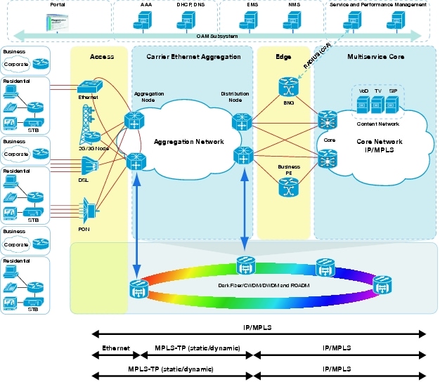
The Metro Ethernet Forum (MEF) is an industry organization dedicated to furthering the deployment of carrier Ethernet services. Ethernet began life as a LAN then expanded to the MAN and is now truly a WAN with many carriers offering services that span the globe. The MEF specifies the Ethernet user network interface (E-UNI) and the network services (E-Line, E-LAN and E-Tree). The E-UNI is the service demarc and is defined to be a standard Ethernet interface. The access technology and core network technology is not defined by the MEF, allowing the carrier to select the right technology for its network. Service attributes are defined for each service, so carrier offerings can be compared even though different technology may be used to implement the service.


Carrier Ethernet is a marketing term for extensions to Ethernet to enable telecommunications network providers ("common carriers" in US industry jargon) to provide Ethernet services to customers and to utilize Ethernet technology in their networks.


Network Implementations:

Access
Aggregation
Core
Ethernet LAN
Metro Ethernet
Carrier Ethernet


Carrier Ethernet is equipment that leverages the heritage of Ethernet while extending it with features that make Ethernet useful in mission-critical transport networks.  These extensions, predominantly covered in the IEEE 802.1a set of standards, include enhanced scalability and OAM capabilities.  Carrier Ethernet supports features needed in a transport network such as connectivity verification, rapid recovery, and performance measurement.

The key features and benefits of Carrier Ethernet include:

  • Well Known Technology – Carrier Ethernet leverages and extends all the features, including low cost, of traditional Ethernet
  • LAN Services in the WAN  – emulates popular LAN and point-to-point Ethernet services
  • Scalability – scales to 1000s of endpoints
  • Convergence – a common platform for IP-based voice, data and video services

There’s no doubt that Ethernet is the service interface of the future. The native protocol for all new devices is moving toward Ethernet – voice, video and data. Until now, the only challenge in deploying a pure Ethernet infrastructure was quality of service.

Carrier Ethernet has finally met that challenge. It offers a great user experience for triple play services, promises new service revenues with user bandwidth profiles and provides carrier class reliability. 
On top of that Carrier Ethernet is simple and inexpensive, making it a perfect platform for delivering the triple play.
  • Networks must support carrier class QoS
    • Carrier Ethernet has the ability to prioritize data, voice and video to provide a superior user experience, flexible mapping service queues
    • Carrier Ethernet can segregate users and provide bandwidth profiles, multistage hierarchical scheduling/shaping
    • Carrier Ethernet provides 50 msec resiliency
  • Network must provide circuit-based visibility
    • Carrier Ethernet allows per-circuit performance monitoring
    • Carrier Ethernet provides Service Based OAM
  • Networks must be flexible
    • Carrier Ethernet offers MPLS
    • Carrier Ethernet allows topology independent
    • Carrier Ethernet allows technology and protocol independent


Services:

E-Line – Ethernet Line. A service connecting two customer Ethernet ports over a WAN.


E-LAN – Ethernet LAN. A multipoint service connecting a set of customer endpoints, giving the appearance to the customer of a bridged Ethernet network connecting the sites.


E-Tree – Ethernet Tree. A multipoint service connecting one or more roots and a set of leaves, but preventing inter-leaf communication.


Summary of the services:


Deployment:

Mobile Backhaul, Triple-Play Backhaul, High-Performance Data Center with E-Line services.

Future Reading:


CCDA 640-864 Official Cert Guide - Chapter 3 Summary


Enterprise Campus:

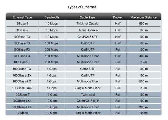
LAN Media: by IEEE 802.3


LAN Hardware:

Repeaters, HUB, Bridge, Switch, Router, L3 Switch.

repeater is an electronic device that receives a signal and retransmits it at a higher level and/or higher power, or onto the other side of an obstruction, so that the signal can cover longer distances.

An Ethernet hub, active hub, network hub, repeater hub or hub is a device for connecting multiple Ethernet devices together and making them act as a single network segment. A hub works at the physical layer (layer 1) of the OSI model. The device is a form of multiport repeater. Repeater hubs also participate in collision detection, forwarding a jam signal to all ports if it detects a collision. The difference is that hubs have more ports than basic repeaters.

A network bridge connects multiple network segments at the data link layer (Layer 2) of the OSI model. In Ethernet networks, the term bridge formally means a device that behaves according to the IEEE 802.1D standard. A bridge and a switch are very much alike; a switch being a bridge with numerous ports. Switch or Layer 2 switch is often used interchangeably with bridge.

router is a device that forwards data packets between computer networks, creating an overlay internetwork. A router is connected to two or more data lines from different networks. When a data packet comes in on one of the lines, the router reads the address information in the packet to determine its ultimate destination. Then, using information in its routing table or routing, it directs the packet to the next network on its journey. Routers perform the "traffic directing" functions on the Internet. A data packet is typically forwarded from one router to another through the networks that constitute the internetwork until it gets to its destination node.

Within the confines of the Ethernet physical layer, a layer 3 switch can perform some or all of the functions normally performed by a router. The most common layer-3 capability is awareness of IP multicast through IGMP snooping.


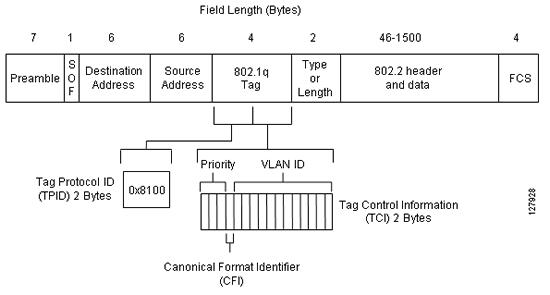
Inter-Switch Link and IEEE 802.1Q Frame Format:


RPVST+


CGMP

Cisco Group Management Protocol is a Cisco proprietary protocol implemented to control multicast traffic at Layer 2. Because a Layer 2 switch is unaware of Layer 3 IGMP messages, it cannot keep multicast packets from being sent to all ports. You must also enable the router to speak CGMP with the LAN switches. With CGMP, switches distribute multicast sessions to the switch ports that have group members.


IGMP Snooping

IGMP snooping is the process of listening to Internet Group Management Protocol (IGMP) network traffic. IGMP snooping, as implied by the name, is a feature that allows a network switch to listen in on the IGMP conversation between hosts and routers. By listening to these conversations the switch maintains a map of which links need which IP multicast streams. Multicasts may be filtered from the links which do not need them.


Sunday, December 25, 2011

CCDA 640-864 Official Cert Guide - Chapter 2 Summary


Hierarchical Network Design Overview

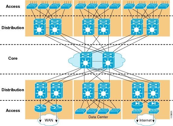
You can use the hierarchical model to design a modular topology using scalable "building blocks" that allow the network to meet evolving business needs. The modular design makes the network easy to scale, understand, and troubleshoot by promoting deterministic traffic patterns.
Cisco introduced the hierarchical design model, which uses a layered approach to network design in 1999 (see Figure 1). The building block components are the access layer, the distribution layer, and the core (backbone) layer. The principal advantages of this model are its hierarchical structure and its modularity.

Figure 1 Hierarchical Campus Network Design:


In a hierarchical design, the capacity, features, and functionality of a specific device are optimized for its position in the network and the role that it plays. This promotes scalability and stability. The number of flows and their associated bandwidth requirements increase as they traverse points of aggregation and move up the hierarchy from access to distribution to core. Functions are distributed at each layer. A hierarchical design avoids the need for a fully-meshed network in which all network nodes are interconnected.
The building blocks of modular networks are easy to replicate, redesign, and expand. There should be no need to redesign the whole network each time a module is added or removed. Distinct building blocks can be put in-service and taken out-of-service without impacting the rest of the network. This capability facilitates troubleshooting, problem isolation, and network management.

Core Layer

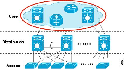
In a typical hierarchical model, the individual building blocks are interconnected using a core layer. The core serves as the backbone for the network, as shown in Figure 2. The core needs to be fast and extremely resilient because every building block depends on it for connectivity. Current hardware accelerated systems have the potential to deliver complex services at wire speed. However, in the core of the network a "less is more" approach should be taken. A minimal configuration in the core reduces configuration complexity limiting the possibility for operational error.
Figure 2 Core Layer:


Although it is possible to achieve redundancy with a fully-meshed or highly-meshed topology, that type of design does not provide consistent convergence if a link or node fails. Also, peering and adjacency issues exist with a fully-meshed design, making routing complex to configure and difficult to scale. In addition, the high port count adds unnecessary cost and increases complexity as the network grows or changes. The following are some of the other key design issues to keep in mind:
•Design the core layer as a high-speed, Layer 3 (L3) switching environment utilizing only hardware-accelerated services. Layer 3 core designs are superior to Layer 2 and other alternatives because they provide:
–Faster convergence around a link or node failure.
–Increased scalability because neighbor relationships and meshing are reduced.
–More efficient bandwidth utilization.
•Use redundant point-to-point L3 interconnections in the core (triangles, not squares) wherever possible, because this design yields the fastest and most deterministic convergence results.
•Avoid L2 loops and the complexity of L2 redundancy, such as Spanning Tree Protocol (STP) and indirect failure detection for L3 building block peers.

Distribution Layer

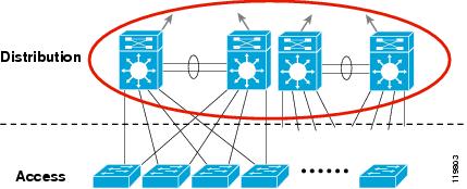
The distribution layer aggregates nodes from the access layer, protecting the core from high-density peering (see Figure 3). Additionally, the distribution layer creates a fault boundary providing a logical isolation point in the event of a failure originating in the access layer. Typically deployed as a pair of L3 switches, the distribution layer uses L3 switching for its connectivity to the core of the network and L2 services for its connectivity to the access layer. Load balancing, Quality of Service (QoS), and ease of provisioning are key considerations for the distribution layer.
Figure 3 Distribution Layer:


High availability in the distribution layer is provided through dual equal-cost paths from the distribution layer to the core and from the access layer to the distribution layer (see Figure 4). This results in fast, deterministic convergence in the event of a link or node failure. When redundant paths are present, failover depends primarily on hardware link failure detection instead of timer-based software failure detection. Convergence based on these functions, which are implemented in hardware, is the most deterministic.

Figure 4 Distribution Layer—High Availability:


L3 equal-cost load sharing allows both uplinks from the core to the distribution layer to be utilized. The distribution layer provides default gateway redundancy using the Gateway Load Balancing Protocol (GLBP), Hot Standby Router Protocol (HSRP), or Virtual Router Redundancy Protocol(VRRP). This allows for the failure or removal of one of the distribution nodes without affecting end point connectivity to the default gateway.
You can achieve load balancing on the uplinks from the access layer to the distribution layer in many ways, but the easiest way is to use GLBP. GLBP provides HSRP-like redundancy and failure protection. It also allows for round robin distribution of default gateways to access layer devices, so the end points can send traffic to one of the two distribution nodes.

Access Layer
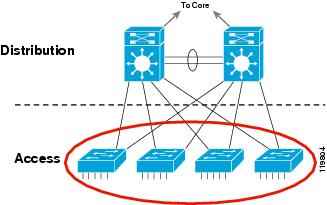
The access layer is the first point of entry into the network for edge devices, end stations, and IP phones (see Figure 5). The switches in the access layer are connected to two separate distribution layer switches for redundancy. If the connection between the distribution layer switches is an L3 connection, then there are no loops and all uplinks actively forward traffic.
Figure 5 Access Layer:

A robust access layer provides the following key features:
•High availability (HA) supported by many hardware and software attributes.
•Inline power (POE) for IP telephony and wireless access points, allowing customers to converge voice onto their data network and providing roaming WLAN access for users.
•Foundation services.
The hardware and software attributes of the access layer that support high availability include the following:
•System-level redundancy using redundant supervisor engines and redundant power supplies. This provides high-availability for critical user groups.
•Default gateway redundancy using dual connections to redundant systems (distribution layer switches) that use GLBP, HSRP, or VRRP. This provides fast failover from one switch to the backup switch at the distribution layer.
•Operating system high-availability features, such as Link Aggregation (EtherChannel or 802.3ad), which provide higher effective bandwidth while reducing complexity.
•Prioritization of mission-critical network traffic using QoS. This provides traffic classification and queuing as close to the ingress of the network as possible.
•Security services for additional security against unauthorized access to the network through the use of tools such as 802.1x, port security, DHCP snooping, Dynamic ARP Inspection, and IP Source Guard.
•Efficient network and bandwidth management using software features such as Internet Group Membership Protocol (IGMP) snooping. IGMP snooping helps control multicast packet flooding for multicast applications.

For more information:


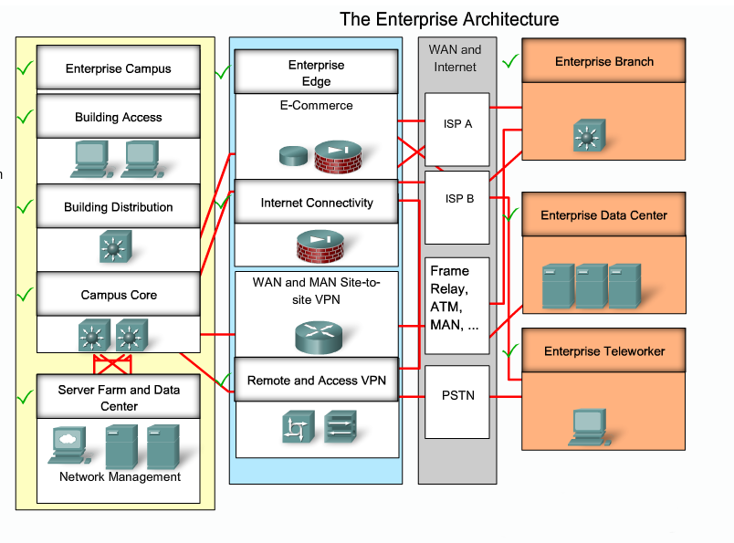
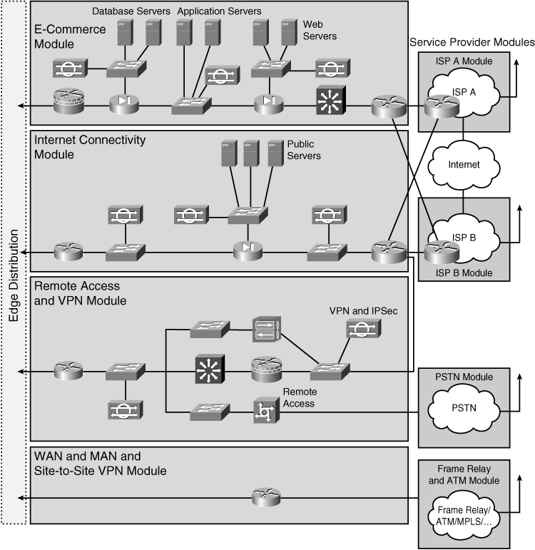
Cisco Enterprise Architecture Model


Enterprise Campus Module


Enterprise Edge Area


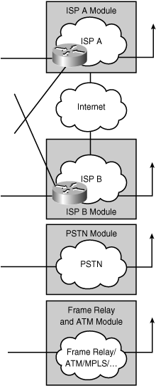
Service Provider Function Area


High availability network services


CCDA 640-864 Official Cert Guide - Chapter 1 Summary

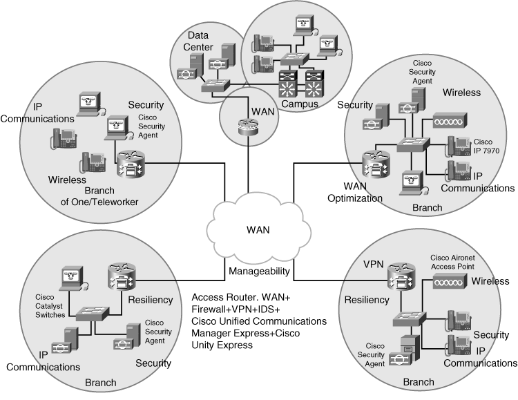
Cisco Architectures for the Enterprise
Business forces affecting decisions for the enterprise network include the following:
  • Return on investment
  • Regulation
  • Competitiveness
  • Removal of borders
  • Virtualization
  • Growth of applications


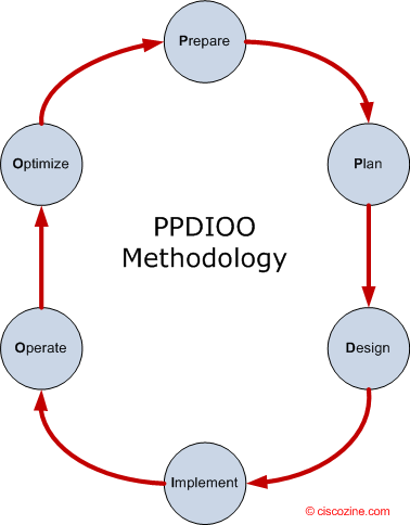
PPDIOO Phase Description
Prepare - Establishes organization and business requirements, develops a network strategy, and proposes a high-level architecture
Plan - Identifies the network requirements by characterizing and assessing the network, performing a gap analysis
Design - Provides high availability, reliability, security, scalability, and performance
Implement Installation and configuration of new equipment
Operate - Day-to-day network operations
Optimize - Proactive network management; modifications to the design

The following sections focus on a design methodology for the first three phases of the PPDIOO methodology. This design methodology has three steps:
Step 1. Identifying customer network requirements – Talking to all the people.
Step 2. Characterizing the existing network – Collecting Network information.
Step 3. Designing the network topology and solutions


Designing the Network Topology and Solutions:
Top – down design just means starting your design from the top layer of the OSI model and working your way down. Top-down design adapts the network and physical infrastructure to the network application’s needs. With a top-down approach, network devices and technologies are not selected until the applications’ requirements are analyzed.


MPLS-TP

MPLS-TP or MPLS Transport Profile is a profile of MPLS whose definition has been commenced by the IETF.

Provide Connection Oriented transport for packet and TDM packets. MPLS-TP is MPLS!!!


MPLS-TP is to be based on the same architectural principles of layered networking that are used in longstanding transport network technologies like SDHSONET and OTN. Service providers have already developed management processes and work procedures based on these principles.
MPLS-TP will provide service providers with a reliable packet-based technology that is based upon circuit-based transport networking, and thus is expected to align with current organizational processes and large-scale work procedures similar to other packet transport technologies.
MPLS-TP is expected to be a low cost L2 technology (if the limited profile to be specified is implemented in isolation) that will provide QoS, end-to-end OA&M and protection switching.

Implementation in:
MPLS-TP => RAN (replaces old backhaul technologies)
MPTL-TE => IP Core (L3VPN)

Characteristics:
1)      Connection Oriented
2)      Client Agnostics
3)      Physical Agnostics
4)      OAM Function
5)      Several Protection Scheme
6)      Network Provisioning (Control Plane)


Packet Transport evolution:

1)      Ethernet (IEEE 802.3)
2)      Carrier Ethernet:
a.       Connection-Less:
                                                              i.      802.1q – VLAN
                                                            ii.      802.1ad – Provider Bridge
                                                          iii.      802.1ag – Connectivity Fault
                                                          iv.      802.1ah – Provider Backbone
b.      Connection-Oriented
                                                              i.      Pseudo Wire
3)      MPLS
a.       Pseudo Wire
b.      T-MPLS (FAIL)
c.       PBB-TE (FAIL)
d.   MPLS-TP!!! – Selected.


Optical Transport Technology

Brief explanation about Optical Transport Technologies:

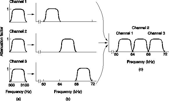
FDM
Frequency-Division Multiplexing (FDM) is a form of signal multiplexing which involves assigning non-overlapping frequency ranges to different signals or to each "user" of a medium.


TDM and PDH
Time-Division Multiplexing (TDM) is a type of digital (or rarely analogmultiplexing in which two or more bit streams or signals are transferred apparently simultaneously as sub-channels in one communication channel, but are physically taking turns on the channel. The time domain is divided into several recurrent timeslots of fixed length, one for each sub-channel. A sample byte or data block of sub-channel 1 is transmitted during timeslot 1, sub-channel 2 during timeslot 2, etc. One TDM frame consists of one timeslot per sub-channel plus a synchronization channel and sometimes error correction channel before the synchronization. After the last sub-channel, error correction, and synchronization, the cycle starts all over again with a new frame, starting with the second sample, byte or data block from sub-channel 1, etc.


The Plesiochronous Digital Hierarchy (PDH) system, also known as the PCM system, for digital transmission of several telephone calls over the same four-wire copper cable (T-carrier or E-carrier) or fiber cable in the circuit switched digital telephone network.


The PDH system effectively develops the idea of primary multiplexing using time
Division Multiplexing (TDM) to generate faster signals. This is done in stages by first combining (multiplexing) E1 or T1 links into what are known as E2 or T2 links, and if required, going even further by combining (multiplexing) E2 or T2 links, etc.

This multiplexing hierarchy is known as the Plesiochronous Digital Hierarchy (PDH). Plesiochronous, meaning “almost synchronous,” relates to the inputs that can be of slightly varying speeds relative to each other and the system’s ability to cope with the differences.

These groups of signals can be transmitted as an electrical signal over a coaxial cable, as radio signals, or optically via fiber-optic systems. As such, PDH formed the backbone of early optical networks.

The aggregate signal can be sent to line at any stage of the hierarchy, using the appropriate transmission medium and modulation techniques.

The big issue with this multiplexing technology is to drop or add 2Mbps interfae (another E1) to the ring need to implement the equipments all the way down from the ~140Mbps to the 2M multiplexer.

Line rates:

SDH-SONET
Synchronous Optical Networking (SONET) and Synchronous Digital Hierarchy (SDH) are standardized multiplexing protocols that transfer multiple digital bit streams over optical fiber using lasers or highly coherent light from light-emitting diodes (LEDs). At low transmission rates data can also be transferred via an electrical interface. The method was developed to replace the Plesiochronous Digital Hierarchy (PDH) system for transporting large amounts of telephone calls and data traffic over the same fiber without synchronization problems.

Both SDH and SONET are widely used today: SONET in the United States and Canada, and SDH in the rest of the world. Although the SONET standards were developed before SDH, it is considered a variation of SDH because of SDH's greater worldwide market penetration.
The SDH standard was originally defined by the European Telecommunications Standards Institute (ETSI), and is formalized as International Telecommunication Union (ITU) standards.


NG-SDH/SONET
SONET/SDH development was originally driven by the need to transport multiple PDH signals—like DS1, E1, DS3, and E3—along with other groups of multiplexed 64 kbit/s pulse-code modulated voice traffic. The ability to transport ATM traffic was another early application. In order to support large ATM bandwidths, concatenation was developed, whereby smaller multiplexing containers (e.g., STS-1=STS-3C/3=52Mbps (also named STM-0)) are inversely multiplexed to build up a larger container (e.g., STS-3c) to support large data-oriented pipes.
Basically Next Generation SDH should helps us to send Ethernet traffic in more efficient way over the SDH/SONET technology.
One problem with traditional concatenation, however, is inflexibility. Depending on the data and voice traffic mix that must be carried, there can be a large amount of unused bandwidth left over, due to the fixed sizes of concatenated containers. For example, fitting a 100 Mbit/s Fast Ethernet connection inside a 155 Mbit/s STS-3c container leads to considerable waste. More important is the need for all intermediate network elements to support newly-introduced concatenation sizes. This problem was overcome with the introduction of Virtual Concatenation.
Virtual concatenation (VCAT) allows for a more arbitrary assembly of lower-order multiplexing containers, building larger containers of fairly arbitrary size (e.g., 100 Mbit/s) without the need for intermediate network elements to support this particular form of concatenation. Virtual concatenation leverages the X.86 or Generic Framing Procedure (GFP) protocols in order to map payloads of arbitrary bandwidth into the virtually-concatenated container.
The Link Capacity Adjustment Scheme (LCAS) allows for dynamically changing the bandwidth via dynamic virtual concatenation, multiplexing containers based on the short-term bandwidth needs in the network.
The set of next-generation SONET/SDH protocols that enable Ethernet transport is referred to as Ethernet over SONET/SDH (EoS).


MSPP
 Multi-Service Provisioning Platform, MSPPs enable service providers to offer customers new bundled services at the transport, switching and routing layers of the network, and they dramatically decrease the time it takes to provision new services while improving the flexibility of adding, migrating or removing customers.
These provisioning platforms allow service providers to simplify their edge networks by consolidating the number of separate boxes needed to provide intelligent optical access. They drastically improve the efficiency of SONET networks for transporting multiservice traffic.
The platforms also reduce the number of network management systems needed, and decrease the resources needed to install, provision and maintain the network.
MSPPs are very complex systems, involving a variety of hardware and software technologies, millions of lines of code and a range of functionality. Each vendor's approach is unique and optimized to solve a specific set of problems.
Because MSPPs are close to the customer, they must interface with a variety of customer premises equipment and handle a range of physical interfaces. Most vendors support telephony interfaces (DS-1, DS-3), optical interfaces (OC-3, OC-12), and Ethernet interfaces (10/100Base-T). DSL and Gigabit Ethernet interfaces may also be offered.
MSPP offers SDH services E-LAN and Multipoint to Multipoint.

WDM
 Early fiber optic transmission systems put information onto strands of glass through simple pulses of light. A light was flashed on and off to represent the “ones” and “zeros” of digital information. The actual light could be of almost any wavelength (also known as color or frequency) from roughly 670nm to 1550nm.
During the 1980s, fiber optic data communications modems used low-cost LEDs to put near-infrared pulses onto low-cost fiber. As the need for information increased, the need for bandwidth also increased. Early SONET systems used 1310nm lasers to deliver 155 Mb/s data streams over very long distances. But this capacity was quickly exhausted. Advances in optoelectronic components allowed design of systems that simultaneously transmitted multiple wavelengths of light over a single fiber. Multiple high-bit rate data streams of 2.5 Gb/s, 10 Gb/s and, more recently, 40 Gb/s and 100Gb/s could be multiplexed through divisions of several wavelengths. And so was born Wavelength Division Multiplexing (WDM).

In fiber-optic communications, wavelength-division multiplexing (WDM) is a technology which multiplexes a number of optical carrier signals onto a single optical fiber by using different wavelengths (i.e colours) of laser light. This technique enables bidirectional communications over one strand of fiber, as well as multiplication of capacity.
The term wavelength-division multiplexing is commonly applied to an optical carrier (which is typically described by its wavelength), whereas frequency-division multiplexing typically applies to a radio carrier (which is more often described by frequency). Since wavelength and frequency are tied together through a simple directly inverse relationship, the two terms actually describe the same concept.

DWDM and CWDM

CWDM - Coarse Wavelength Division Multiplexing. WDM systems with fewer than eight active wavelengths per fiber.

DWDM - Dense Wavelength Division Multiplexing. WDM systems with more than eight active wavelengths per fiber.

Types of WDM
Currently, there are two types of WDM in existence today: Coarse WDM (CWDM) and Dense
WDM (DWDM). Backwards as it may seem, DWDM came well before CWDM, which appeared only after a booming telecommunications market drove prices to affordable lows. Whereas CWDM breaks the spectrum into big chunks, DWDM dices it finely. DWDM fits 40-plus channels into the same frequency range used for two CWDM channels.
CWDM is defined by wavelengths. DWDM is defined in terms of frequencies. DWDM’s tighter wavelength spacing fit more channels onto a single fiber, but cost more to implement and operate.

Distinctive CWDM differences
CWDM can—in principle—match the basic capabilities of DWDM but at lower capacity and lower cost. CWDM enables carriers to respond flexibly to diverse customer needs in metropolitan regions where fiber may be at a premium. However, it’s not really in competition with DWDM as both fulfill distinct roles that largely depend upon carrier-specific circumstances and requirements anyway. The point and purpose of CWDM is short-range communications. It uses wide-range frequencies and spreads wavelengths far apart from each other. Standardized channel spacing permits room for wavelength drift as lasers heat up and cool down during operation. By design, CWDM equipment is compact and cost-effective as compared to DWDM designs.

Distinctive DWDM differences
DWDM is designed for long-haul transmission where wavelengths are packed tightly together. Vendors have found various techniques for cramming 32, 64, or 128 wavelengths into a fiber. When boosted by Erbium Doped-Fiber Amplifiers (EDFAs)—a sort of performance enhancer for high-speed communications—these systems can work over thousands of kilometers. Densely packed channels aren’t without their limitations. First, high-precision filters are required to peel away one specific wavelength without interfering with neighboring wavelengths. Those don’t come cheap. Second, precision lasers must keep channels exactly on target. That nearly always means such lasers must operate at a constant temperature. High-precision, high-stability lasers are expensive, as are related cooling systems.

OTN

OTN was designed to provide support for optical networking using wavelength-division multiplexing (WDM) unlike its predecessorSONET/SDH.
ITU-T Recommendation G.709 is commonly called Optical Transport Network (OTN) (also called digital wrapper technology or optical channel wrapper). As of December 2009 OTN has standardized the following line rates.

  • OTU0 is currently under development to transport a 1 GbE signal.
  • OTU1 has a line rate of approximately 2.7 Gbit/s and was designed to transport a SONETOC-48 or synchronous digital hierarchy (SDH) STM-16 signal.
  • OTU2 has a line rate of approximately 10.7 Gbit/s and was designed to transport an OC-192STM-64 or 10Gbit/s WAN. OTU2 can be overclocked (non standard) to carry signals faster than STM64/OC192 (9.953 Gbit/s) like 10 gigabit Ethernet LAN PHY coming from IP/Ethernet switches and routers at full line rate (10.3 Gbit/s). This is specified in G.Sup43 and called OTU2e.
  • OTU3 has a line rate of approximately 43 Gbit/s and was designed to transport an OC-768or STM-256 signal.[2]
  • OTU4 has a line rate of approximately 112 Gbit/s and was designed to transport a 100 Gigabit Ethernet signal.

ASON

ASON (Automatically Switched Optical Network) is a concept for the evolution of transport networks which allows for dynamic policy-driven control of an optical or SDH network based on signaling between a user and components of the network. [1] Its aim is to automate the resource and connection management within the network. The IETF defines ASON as an alternative/supplement to NMS based connection management

While ITU has worked on the requirements and architecture of ASON based on the requirements on its members, it is explicitly aiming to avoid the development of new protocols, when existing ones will work fine. The IETF, on the other hand, has been tasked with the development of new protocols in response to general industry requirement. Therefore, while ITU already include the PNNI protocol for signaling in the Control plane, IETF has been developing GMPLS as a second option protocol to be used in the Control Plane for signalling.  As a product of IETF, GMPLS (Generalized MPLS) uses IP to communicate between different components in the Control Plane.

Thats it... (sponsored by Wiki..)