Wireless LAN Technologies
WLAN Standards
ISM and UNII Frequencies
ISM - Industrial, Scientific and medical - frequencies are
set aside by ITU-R radio regulations 5.138 and 5.150. In the U.S., the
Federal Communications Commission (15.247) specifies the ISM bands for
unlicensed use. Several bands are specified in the following ranges:
900 to 928 MHz
2.4 to 2.5 GHz
5.75 to 5.875 GHz
Of these, channels located in the 2.4-GHz range are used for 802.11b and
802.11g. As shown in Figure above, 11 overlapping channels are available for use.
Each channel is 22 MHz wide. It is common to use channels 1, 6, and 11 in the
same areas, because these three channels do not overlap.
The UNII - Unlicensed National Information Infrastructure -
radio bands were specified for use with 802.11a wireless. UNII operates over
three ranges:
UNII 1—5.15 to 5.25 GHz and 5.25
to 5.35 GHz.
UNII 2—5.47 to 5.725 GHz. This
range is used by High Performance Radio LAN (HiperLAN) in Europe.
UNII 3—5.725 to 5.875 GHz. This
range overlaps with ISM.
UNII provides 12 nonoverlapping channels for 802.11a.
WLAN Standards summary
| IEEE Protocol | Release | Frequency | Typical Data rate | Max. Data Rate |
|---|
| Legacy | 1997 | ISM | 1 Mbps | 2 Mbps |
| 802.11a | 1999 | UNII | 25 Mbps | 54 Mbps |
| 802.11b | 1999 | ISM | 6,5 Mbps | 11 Mbps |
| 802.11g | 2003 | ISM | 25 Mbps | 54 Mbps |
| 802.11n | 2007 (Draft) | ISM or UNII | 200 Mbps | 540 Mbps |
Service Set Identifier
A service set is all the
devices associated with a local or enterprise IEEE 802.11 wireless local
area network (WLAN). An SSID is the name of a
wireless local area network (WLAN). All wireless devices on a WLAN must employ
the same SSID in order to communicate with each other.
Cisco Unified Wireless Network
- Client
devices: With more than 90 percent of shipping client devices
certified as Cisco Compatible under the CCX program, almost any client
device that is selected will support the Cisco UWN advanced features.
- Lightweight
APs: Dynamically configured APs provide ubiquitous network access
in all environments. Enhanced productivity is supported through
plug-and-play with the LWAPP used between the APs and the Cisco WLCs.
Cisco APs are a proven platform with a large installed base and market
share leadership. All Cisco lightweight APs support mobility services,
such as fast secure roaming for voice, and location services for real-time
network visibility.
- Network
unification: Integration of wired and wireless networks is
critical for unified network control, scalability, security, and
reliability. Seamless functionality is provided through wireless
integration into all major switching and routing platforms.
- Network
management: The same level of security, scalability, reliability,
ease of deployment, and management for WLANs as wired LANs is provided
through network management systems such as the Cisco WCS, which helps
visualize and secure the airspace. The Cisco wireless location appliance
provides location services.
- Mobility
services: Unified mobility services include advanced security
threat detection and mitigation, voice services, location services, and
guest access.

Lightweight Access Point Protocol or LWAPP is
the name of a protocol that can control multiple Wi-Fi wireless access points at once. This can
reduce the amount of time spent on configuring, monitoring or troubleshooting a
large network. The system will also allow network administrators to closely
analyze the network.
This system is installed in a central server that gathers
data from RF devices from different brands and settings. The server can command
a selected group of devices to apply given settings simultaneously.
Note: Layer 2 LWAPP tunnels use EtherType code 0xBBBB. Layer
3 LWAPP uses UDP ports 12222 and 12223.
Layer 3 LWAPP
CAPWAP
CAPWAP - Control and provisioning of wireless
access points. The protocol specification is described in RFC5415 and an IEEE
802.11 binding is provided in RFC5416 and is based on LWAPP (Lightweight
Access Point Protocol).
CAPWAP is a standard, interoperable protocol that enables a
controller to manage a collection of wireless access points, and uses UDP ports
5246 and 5247.
Cisco Unified Wireless Network Split-MAC Architecture
CAPWAP, which is based on
LWAPP, is a standard, interoperable protocol that enables a controller to
manage a collection of wireless access points. CAPWAP is being implemented in
controller software release 5.2 for these reasons:
- To provide an upgrade path from Cisco products
that use LWAPP to next-generation Cisco products that use CAPWAP
- To manage RFID readers and similar devices
- To enable controllers to interoperate with
third-party access points in the future
LWAPP-enabled access points
can discover and join a CAPWAP controller, and conversion to a CAPWAP
controller is seamless. For example, the controller discovery process and the
firmware downloading process when you use CAPWAP are the same as when you use
LWAPP. The one exception is for Layer 2 deployments, which are not supported by
CAPWAP.
You can deploy CAPWAP
controllers and LWAPP controllers on the same network. The CAPWAP-enabled
software allows access points to join either a controller that runs CAPWAP or
LWAPP. The only exception is the Cisco Aironet 1140 Series Access Point, which
supports only CAPWAP and therefore joins only controllers that run CAPWAP. For
example, an 1130 series access point can join a controller that runs either
CAPWAP or LWAPP whereas an 1140 series access point can join only a controller
that runs CAPWAP.
Access Point Modes
- Local mode—This is the default mode of
operation. When an LAP is placed into local mode, the AP will transmit on
the normally assigned channel. However, the AP also monitors all other
channels in the band over a period of 180 seconds to scan each of the other
channels for 60ms during the non-transmit time. During this time, the AP
performs noise floor measurements, measures interference, and scans for
IDS events.
- REAP mode—Remote Edge Access Point (REAP)
mode enables an LAP to reside across a WAN link and still be able to
communicate with the WLC and provide the functionality of a regular LAP.
REAP mode is supported only on the 1030 LAPs.
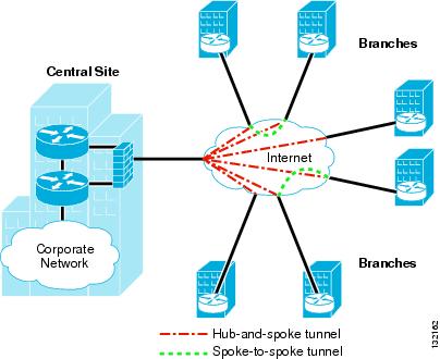
- H-REAP Mode— H-REAP is a wireless solution
for branch office and remote office deployments. H-REAP enables customers
to configure and control access points (APs) in a branch or remote office
from the corporate office through a WAN link without the need to deploy a
controller in each office. H-REAPs can switch client data traffic locally
and perform client authentication locally when the connection to the
controller is lost. When connected to the controller, H-REAPs can also
tunnel traffic back to the controller.
- Monitor mode—Monitor mode is a feature
designed to allow specified LWAPP-enabled APs to exclude themselves from
handling data traffic between clients and the infrastructure. They instead
act as dedicated sensors for location based services (LBS), rogue access
point detection, and intrusion detection (IDS). When APs are in Monitor
mode they cannot serve clients and continuously cycle through all
configured channels listening to each channel for approximately 60 ms.
- Rogue
detector mode—LAPs that operate in Rogue Detector mode monitor the rogue
APs. They do not transmit or contain rogue APs. The idea is that the rogue
detector should be able to see all the VLANs in the network since rogue
APs can be connected to any of the VLANs in the network (thus we connect
it to a trunk port). The switch sends all the rogue AP/Client MAC address
lists to the Rogue Detector (RD). The RD then forwards those up to the WLC
in order to compare with the MACs of clients that the WLC APs have heard
over the air. If MACs match, then the WLC knows the rogue AP to which
those clients are connected is on the wired network.
- Sniffer
mode—An LWAPP that operates in Sniffer mode functions as a sniffer and
captures and forwards all the packets on a particular channel to a remote
machine that runs Airopeek. These packets contain information on
timestamp, signal strength, packet size and so on. The Sniffer feature can
be enabled only if you run Airopeek, which is a third-party network
analyzer software that supports decoding of data packets.
- Bridge
Mode— Bridge mode is used when the access points are setup in a mesh
environment and used to bridge between each other.
WLAN Authentication
Authentication Options
After the wireless client associates to the AP, the AP
blocks the client from gaining access to anything on the network, except the
authentication server, until the client has logged in and authenticated. The
client (the supplicant) supplies network login credentials such as a user ID
and password to the authenticator (the WLC). The supplicant, the authenticator,
and the authentication server participate in the authentication process. If the
authentication process succeeds, the authenticator allows network access to the
supplicant through the appropriate port. The WLC tells the lightweight AP which
dynamic interface (as described in the “WLC Interfaces” section later in this
chapter) and policies to use for the client.
After mutual authentication has been
successfully completed, the client and RADIUS server each derive the same
encryption key, which is used to encrypt all data exchanged between the client
and the WLC. Using a secure channel on the wired LAN, the RADIUS server sends
the key to WLC, which stores and uses it when communicating with the client.
The result is per-user, per-session encryption keys, with the length of a session
determined by a policy defined on the RADIUS server. When a session expires or
the client roams from one AP to another, a reauthentication occurs and
generates a new session key. The reauthentication is transparent to the user.
Several
802.1X authentication types exist, each providing a different approach to
authentication while relying on the same framework and EAP for communication
between a client and the authentication server. Cisco UWN EAP support includes
the following types:
- EAP-Transport
Layer Security (EAP-TLS): EAP-TLS is an Internet Engineering Task
Force (IETF) open standard that is well supported among wireless vendors
but rarely deployed. It uses PKI to secure communications to the RADIUS
server using TLS and digital certificates; it requires certificates on
both the server and client.
- EAP-Tunneled
TLS (EAP-TTLS): EAP-TTLS was codeveloped by Funk Software and
Certicom. It is widely supported across platforms and offers very good
security. EAP-TTLS uses PKI certificates only on the RADIUS authentication
server. The authentication of the client is done with a username and
password.
- Protected
Extensible Authentication Protocol (PEAP): PEAP was a joint
proposal by Cisco Systems, Microsoft, and RSA Security as an open
standard. Authentication of the client is done using PEAP-Generic Token
Card (GTC) or PEAP-Microsoft Challenge Handshake Authentication Protocol
version 2 (MSCHAPv2). PEAP-MSCHAPv2 is the most common version and is
widely available in products and widely deployed. It is similar in design
to EAP-TTLS but requires a PKI certificate only on the server to create a
secure TLS tunnel to protect user authentication. PEAP-GTC allows more
generic authentication to a number of databases, such as Novell Directory
Services.
- Cisco
Lightweight Extensible Authentication Protocol (LEAP): LEAP is an
early proprietary EAP method and is supported in the CCX program. It is
vulnerable to dictionary attack.
- Cisco
EAP-Flexible Authentication via Secure Tunneling (EAP-FAST): EAP-FAST
is a proposal by Cisco Systems to fix the weaknesses of LEAP; it is
supported in the CCX program. EAP-FAST uses a protected access credential
(PAC) and optionally uses server certificates. EAP-FAST has three phases.
Phase 0 is an optional phase where the PAC can be provisioned manually or
dynamically. In Phase 1, the client and the AAA server use the PAC to
establish TLS tunnel. In Phase 2, the client sends user information across
the tunnel.
Each EAP type has advantages and
disadvantages. Trade-offs exist between the security provided, manageability,
operating systems supported, client devices supported, client software and
authentication messaging overhead, certificate requirements, user ease of use,
and WLAN infrastructure device support. When selecting an EAP type to use,
considerations include the type of security mechanism used for the security
credentials, the user authentication database, the client operating systems in
use, the available client supplicants, the type of user login needed, and
whether RADIUS or AAA servers are used.
WLAN Controller Components
WLAN - Identified by a unique SSID and assigned to an
interface
Interface - A logical connection that maps to a VLAN in the
wired network
Port - A physical connection to the wired LAN
WLC Interface Types
RF Site Survey
Wireless Mesh for Outdoor Wireless
Outdoor wireless networks deliver real-time access to
people, applications, and network resources, transforming down-time into
productive time.
Whether you're a mobile worker e-mailing a customer from
the airport, a student at a coffee shop downloading a homework assignment on
your PDA, or a police officer viewing a video surveillance camera from a patrol
car, mobility is letting you stay connected, anytime, anywhere.
Cisco outdoor wireless solutions come as small as a
single hot spot for a home office and can grow to high-speed wireless
connectivity across entire cities and counties.
Wireless Mesh Access Points
The Cisco wireless mesh networking solution lets you
deploy cost-effective, scalable outdoor wireless LANs. It doesn't matter
whether you're an individual or a government agency IT manager. There's a
solution for you.
Wireless Bridges
Wireless bridges offer high-speed, building-to-building
or campus connectivity for line-of-sight applications. Wi-Fi bridging solutions
offer an affordable alternative to leased-line services and operate by sharing
LAN/Internet access between two or more sites.
Mobile Networks
The Cisco Mobile Network forms a wireless network in and
around a vehicle. This allows users to roam across different networks in a
metropolitan area while maintaining a secure broadband connection in motion.
It's specifically designed for the secure delivery of data for public safety
and transportation applications.
Campus Design Considerations
Local MAC
REAP
Hybrid REAP
Branch Office Controller Options