Wednesday, January 25, 2012

CCDA 640-864 Official Cert Guide - Chapter 15 Summary


Simple Network Management Protocol
Overview and basic concepts
In typical SNMP uses, one or more administrative computers, called managers, have the task of monitoring or managing a group of hosts or devices on a computer network. Each managed system executes, at all times, a software component called an agent which reports information via SNMP to the manager.
Essentially, SNMP agents expose management data on the managed systems as variables. The protocol also permits active management tasks, such as modifying and applying a new configuration through remote modification of these variables. The variables accessible via SNMP are organized in hierarchies. These hierarchies, and other metadata (such as type and description of the variable), are described by Management Information Bases (MIBs).

An SNMP-managed network consists of three key components:
Managed device
Agent — software which runs on managed devices
Network management system (NMS) — software which runs on the manager
A managed device is a network node that implements an SNMP interface that allows unidirectional (read-only) or bidirectional access to node-specific information. Managed devices exchange node-specific information with the NMSs. Sometimes called network elements, the managed devices can be any type of device, including, but not limited to, routers, access servers, switches, bridges, hubs, IP telephones, IP video cameras, computer hosts, and printers.
An agent is a network-management software module that resides on a managed device. An agent has local knowledge of management information and translates that information to or from an SNMP specific form.
A network management system (NMS) executes applications that monitor and control managed devices. NMSs provide the bulk of the processing and memory resources required for network management. One or more NMSs may exist on any managed network.

Management information base (MIB)
Main article: Management information base
SNMP itself does not define which information (which variables) a managed system should offer. Rather, SNMP uses an extensible design, where the available information is defined by management information bases (MIBs). MIBs describe the structure of the management data of a device subsystem; they use a hierarchical namespace containing object identifiers (OID). Each OID identifies a variable that can be read or set via SNMP. MIBs use the notation defined by ASN.1.

Protocol details

SNMP operates in the Application Layer of the Internet Protocol Suite (Layer 7 of the OSI model). The SNMP agent receives requests on UDP port 161. The manager may send requests from any available source port to port 161 in the agent. The agent response will be sent back to the source port on the manager. The manager receives notifications (Traps and InformRequests) on port 162. The agent may generate notifications from any available port. When used with Transport Layer Security or Datagram Transport Layer Security requests are received on port 10161 and traps are sent to port 10162.
SNMPv1 specifies five core protocol data units (PDUs). Two other PDUs, GetBulkRequest and InformRequest were added in SNMPv2 and carried over to SNMPv3.

All SNMP PDUs are constructed as follows:
IP header         UDP header    version community      PDU-type        request-id        error-status      error-index            variable bindings

The seven SNMP protocol data units (PDUs) are as follows:
GetRequest
A manager-to-agent request to retrieve the value of a variable or list of variables. Desired variables are specified in variable bindings (values are not used). Retrieval of the specified variable values is to be done as an atomic operation by the agent. A Response with current values is returned.
SetRequest
A manager-to-agent request to change the value of a variable or list of variables. Variable bindings are specified in the body of the request. Changes to all specified variables are to be made as an atomic operation by the agent. A Response with (current) new values for the variables is returned.
GetNextRequest
A manager-to-agent request to discover available variables and their values. Returns a Response with variable binding for the lexicographically next variable in the MIB. The entire MIB of an agent can be walked by iterative application of GetNextRequest starting at OID 0. Rows of a table can be read by specifying column OIDs in the variable bindings of the request.
GetBulkRequest
Optimized version of GetNextRequest. A manager-to-agent request for multiple iterations of GetNextRequest. Returns a Response with multiple variable bindings walked from the variable binding or bindings in the request. PDU specific non-repeaters and max-repetitions fields are used to control response behavior. GetBulkRequest was introduced in SNMPv2.
Response
Returns variable bindings and acknowledgement from agent to manager for GetRequest, SetRequest, GetNextRequest, GetBulkRequest and InformRequest. Error reporting is provided by error-status and error-index fields. Although it was used as a response to both gets and sets, this PDU was called GetResponse in SNMPv1.
Trap
Asynchronous notification from agent to manager. Includes current sysUpTime value, an OID identifying the type of trap and optional variable bindings. Destination addressing for traps is determined in an application-specific manner typically through trap configuration variables in the MIB. The format of the trap message was changed in SNMPv2 and the PDU was renamed SNMPv2-Trap.
InformRequest
Acknowledged asynchronous notification manager to manager or agent to manager. Manager-to-manager notifications were already possible in SNMPv1 (using a Trap), but as SNMP commonly runs over UDP where delivery is not assured and dropped packets are not reported, delivery of a Trap was not guaranteed. InformRequest fixes this by sending back an acknowledgement on receipt. Receiver replies with Response parroting all information in the InformRequest. This PDU was introduced in SNMPv2.

Version 1
SNMP version 1 (SNMPv1) is the initial implementation of the SNMP protocol. SNMPv1 operates over protocols such as User Datagram Protocol (UDP), Internet Protocol (IP), OSI Connectionless Network Service (CLNS), AppleTalk Datagram-Delivery Protocol (DDP), and Novell Internet Packet Exchange (IPX). SNMPv1 is widely used and is the de facto network-management protocol in the Internet community.
The first RFCs for SNMP, now known as SNMPv1, appeared in 1988:
RFC 1065 — Structure and identification of management information for TCP/IP-based internets
RFC 1066 — Management information base for network management of TCP/IP-based internets
RFC 1067 — A simple network management protocol
These protocols were obsoleted by:
RFC 1155 — Structure and identification of management information for TCP/IP-based internets
RFC 1156 — Management information base for network management of TCP/IP-based internets
RFC 1157 — A simple network management protocol
After a short time, RFC 1156 (MIB-1) was replaced by more often used:
RFC 1213 — Version 2 of management information base (MIB-2) for network management of TCP/IP-based internets
Version 1 has been criticized for its poor security. Authentication of clients is performed only by a "community string", in effect a type of password, which is transmitted in cleartext. The '80s design of SNMP V1 was done by a group of collaborators who viewed the officially sponsored OSI/IETF/NSF (National Science Foundation) effort (HEMS/CMIS/CMIP) as both unimplementable in the computing platforms of the time as well as potentially unworkable. SNMP was approved based on a belief that it was an interim protocol needed for taking steps towards large scale deployment of the Internet and its commercialization. In that time period Internet-standard authentication/security was both a dream and discouraged by focused protocol design groups.

Version 2
SNMPv2 (RFC 1441–RFC 1452), revises version 1 and includes improvements in the areas of performance, security, confidentiality, and manager-to-manager communications. It introduced GetBulkRequest, an alternative to iterative GetNextRequests for retrieving large amounts of management data in a single request. However, the new party-based security system in SNMPv2, viewed by many as overly complex, was not widely accepted.
Community-Based Simple Network Management Protocol version 2, or SNMPv2c, is defined in RFC 1901–RFC 1908. In its initial stages, this was also informally known as SNMPv1.5. SNMPv2c comprises SNMPv2 without the controversial new SNMP v2 security model, using instead the simple community-based security scheme of SNMPv1. While officially only a "Draft Standard", this is widely considered the de facto SNMPv2 standard.
User-Based Simple Network Management Protocol version 2, or SNMPv2u, is defined in RFC 1909–RFC 1910. This is a compromise that attempts to offer greater security than SNMPv1, but without incurring the high complexity of SNMPv2. A variant of this was commercialized as SNMP v2*, and the mechanism was eventually adopted as one of two security frameworks in SNMP v3.

SNMPv1 & SNMPv2c interoperability
As presently specified, SNMPv2 is incompatible with SNMPv1 in two key areas: message formats and protocol operations. SNMPv2c messages use different header and protocol data unit (PDU) formats from SNMPv1 messages. SNMPv2c also uses two protocol operations that are not specified in SNMPv1. Furthermore, RFC 2576 defines two possible SNMPv1/v2c coexistence strategies: proxy agents and bilingual network-management systems.

Proxy agents
A SNMPv2 agent can act as a proxy agent on behalf of SNMPv1 managed devices, as follows:
A SNMPv2 NMS issues a command intended for a SNMPv1 agent.
The NMS sends the SNMP message to the SNMPv2 proxy agent.
The proxy agent forwards Get, GetNext, and Set messages to the SNMPv1 agent unchanged.
GetBulk messages are converted by the proxy agent to GetNext messages and then are forwarded to the SNMPv1 agent.
The proxy agent maps SNMPv1 trap messages to SNMPv2 trap messages and then forwards them to the NMS.

Bilingual network-management system
Bilingual SNMPv2 network-management systems support both SNMPv1 and SNMPv2. To support this dual-management environment, a management application in the bilingual NMS must contact an agent. The NMS then examines information stored in a local database to determine whether the agent supports SNMPv1 or SNMPv2. Based on the information in the database, the NMS communicates with the agent using the appropriate version of SNMP.

Version 3
Although SNMPv3 makes no changes to the protocol aside from the addition of cryptographic security, its developers have managed to make things look much different by introducing new textual conventions, concepts, and terminology.
SNMPv3 primarily added security and remote configuration enhancements to SNMP.
Security has been the biggest weakness of SNMP since the beginning. Authentication in SNMP Versions 1 and 2 amounts to nothing more than a password (community string) sent in clear text between a manager and agent. Each SNMPv3 message contains security parameters which are encoded as an octet string. The meaning of these security parameters depends on the security model being used.

SNMPv3 provides important security features:
Confidentiality - Encryption of packets to prevent snooping by an unauthorized source.
Integrity - Message integrity to ensure that a packet has not been tampered with in transit including an optional packet replay protection mechanism.
Authentication - to verify that the message is from a valid source.
As of 2004 the IETF recognizes Simple Network Management Protocol version 3 as defined by RFC 3411–RFC 3418 (also known as STD0062) as the current standard version of SNMP. The IETF has designated SNMPv3 a full Internet standard, the highest maturity level for an RFC. It considers earlier versions to be obsolete (designating them "Historic").
In practice, SNMP implementations often support multiple versions: typically SNMPv1, SNMPv2c, and SNMPv3.

RMON

An RMON implementation typically operates in a client/server model. Monitoring devices (commonly called "probes" in this context) contain RMON software agents that collect information and analyze packets. These probes act as servers and the Network Management applications that communicate with them act as clients. While both agent configuration and data collection use SNMP, RMON is designed to operate differently than other SNMP-based systems:
Probes have more responsibility for data collection and processing, which reduces SNMP traffic and the processing load of the clients.
Information is only transmitted to the management application when required, instead of continuous polling.
In short, RMON is designed for "flow-based" monitoring, while SNMP is often used for "device-based" management. RMON is similar to other flow-based monitoring technologies such as NetFlow and SFlow because the data collected deals mainly with traffic patterns rather than the status of individual devices. One disadvantage of this system is that remote devices shoulder more of the management burden, and require more resources to do so. Some devices balance this trade-off by implementing only a subset of the RMON MIB groups (see below). A minimal RMON agent implementation could support only statistics, history, alarm, and event.

The RMON1 MIB consists of ten groups:
  • Statistics: real-time LAN statistics e.g. utilization, collisions, CRC errors
  • History: history of selected statistics
  • Alarm: definitions for RMON SNMP traps to be sent when statistics exceed defined thresholds
  • Hosts: host specific LAN statistics e.g. bytes sent/received, frames sent/received
  • Hosts top N: record of N most active connections over a given time period
  • Matrix: the sent-received traffic matrix between systems
  • Filter: defines packet data patterns of interest e.g. MAC address or TCP port
  • Capture: collect and forward packets matching the Filter
  • Event: send alerts (SNMP traps) for the Alarm group

The RMON2 MIB adds ten more groups:
  • Protocol Directory: list of protocols the probe can monitor
  • Protocol Distribution: traffic statistics for each protocol
  • Address Map: maps network-layer (IP) to MAC-layer addresses
  • Network-Layer Host: layer 3 traffic statistics, per each host
  • Network-Layer Matrix: layer 3 traffic statistics, per source/destination pairs of hosts
  • Application-Layer Host: traffic statistics by application protocol, per host
  • Application-Layer Matrix: traffic statistics by application protocol, per source/destination pairs of hosts
  • User History: periodic samples of user-specified variables
  • Probe Configuration: remote configure of probes
  • RMON Conformance: requirements for RMON2 MIB conformance


NetFlow

NetFlow is a network protocol developed by Cisco Systems for collecting IP traffic information. NetFlow has become an industry standard for traffic monitoring and is supported by platforms other than Cisco IOS and NXOS such as Juniper routers, Enterasys Switches, vNetworking in version 5 of vSphere, Linux, FreeBSD, NetBSD and OpenBSD.

Network Flows
Main article: Packet flow
A network flow has been defined in many ways. The traditional Cisco definition is to use a 7-tuple key, where a flow is defined as a unidirectional sequence of packets all sharing all of the following 7 values:
  • Source IP address
  • Destination IP address
  • Source port for UDP or TCP, 0 for other protocols
  • Destination port for UDP or TCP, type and code for ICMP, or 0 for other protocols
  • IP protocol
  • Ingress interface (SNMP ifIndex)
  • IP Type of Service
  
CDP

The Cisco Discovery Protocol (CDP) is a proprietary Data Link Layer network protocol developed by Cisco Systems. It is used to share information about other directly connected Cisco equipment, such as the operating system version and IP address. CDP can also be used for On-Demand Routing, which is a method of including routing information in CDP announcements so that dynamic routing protocols do not need to be used in simple network.

Syslog

Syslog is a standard for computer data logging. It allows separation of the software that generates messages from the system that stores them and the software that reports and analyzes them.
Syslog can be used for computer system management and security auditing as well as generalized informational, analysis, and debugging messages. It is supported by a wide variety of devices (like printers and routers) and receivers across multiple platforms. Because of this, syslog can be used to integrate log data from many different types of systems into a central repository.
Messages refer to a facility (auth, authpriv, daemon, cron, ftp, lpr, kern, mail, news, syslog, user, uucp, local0, ... , local7 ) and are assigned a severity (Emergency, Alert, Critical, Error, Warning, Notice, Info or Debug) by the sender of the message.
Configuration allows directing messages to various local devices (console), files (/var/log/) or remote syslog daemons. Care must be taken when updating the configuration as omitting or misdirecting message facilities or severities can cause important messages to be ignored by syslog or overlooked by the administrator.
logger is a command line utility that can send messages to the syslog.
Some implementations permit the filtering and display of syslog messages.
Syslog is now standardized within the Syslog working group of the IETF.


Tuesday, January 24, 2012

CCDA 640-864 Official Cert Guide - Chapter 14 Summary


Traditional Voice Architectures

Erlangs
An Erlang is a theoretical unit of measurement used to define the trunking (voice path) utilization in a voice application or environment. Erlangs values are used in Erlang form aggregate trunk usage for a system and do not apply to any specific trunk or call. The hour used for the Erlang calculation should be the busiest hour (peak hour) in the day.
If a group of users makes/receives 20 calls in the average busiest hour and each call lasts and average of 10 minutes, the Erlangs are calculated as follows:

20 calls per hour * 10 minutes per call = 200 minutes per hour
Traffic volume = (200 minutes per hour) / (60 minutes per hour) = 3.33 Erlangs

There are three common Erlang models:
  • Erlang B is a formula that estimates the amount of trunking capacity required given an Erlang value (busy-hour traffic) and a desired Grade of Service (also known as blocking percentage). It is the most common model used. Extending the previous example, 3.33 Erlangs (BHT) and a GoS of 1 percent results in an Erlang B value of nine trunks required. An Erlang B calculator can be found at www.erlang.com/calculator/erlb./
  • Extended Erlang B adds a retry percentage to the Erlang B model. It assumes that some blocked or failed calls will be reattempted, and therefore additional load is added.
  • Erlang C queues excess calls instead of blocking them. This model is used to calculate the number of agents required in a call center environment. It is based on measurements of handling time, expected call volumes, and the amount of time a caller spends with an agent. This model is used in call centers where calls are queued for service.

Centum Call Second
A call second is equivalent to a single call lasting 1 second. A Centum call second (CCS) represents one call occupying a channel for 100 seconds. It is the equivalent of 1/36th of an Erlang. In other words, 36 CCS equals 1 Erlang (3600 seconds). The typical range is around 6 to 12 CCS per port.

Busy Hour
The busy hour is the specific hour within a 24-hour period in which the highest traffic load occurs. Most calls are placed and are of longer durations during this hour. It is also called peak hour.

Busy-Hour Traffic
Busy-hour traffic (BHT) is the amount of voice traffic that occurs in the busy hour, expressed in Erlangs. It is calculated by multiplying the average call duration by the number of calls in the hour and then dividing that by 3600.
For example, if 300 calls occurred during the busy hour, with an average duration of 150 seconds, the BHT is calculated as follows:

BHT = (150 seconds * 300 calls per hour) / (3600 seconds per hour)
BHT = 12.5 Erlangs

Blocking Probability
In voice environments, it is nearly impossible or at least cost-ineffective to provision capacity so that no calls are ever blocked. Therefore, planning for a target GoS is an important aspect in voice networks. The term blocking refers to those calls that cannot be completed due to capacity constraints, usually during peak periods or call spikes.
The blocking probability is the probability that a call will be blocked. Blocking probability is described as a percentage of calls. For example, a blocking probability of 0.02 means that 2 percent of the calls will be blocked, or 20 per every 1000 calls.


Converged Multiservice Networks

IPT Design

Bandwidth
VoIP calls need to meet bandwidth and delay parameters. The amount of bandwidth required depends on the codec used, the Layer 2 protocol, and whether voice-activity detection (VAD) is enabled. For the purpose of call control, you can use the following bandwidth requirements (minimum values) for VoIP design:
G.729 calls use 26 kbps.
G.711 calls use 80 kbps.
When you’re designing for VoIP networks, the total bandwidth for voice, data, and video should not exceed 75 percent sustained of the provisioned link capacity during peak times. Best practice is to provision/plan for no more than one-third of any links for the priority queue/real time traffic. Use the following formula to provision interface speeds:

Link capacity = [required bandwidth for voice] + [required bandwidth for video] + [re-
quired bandwidth for data]

The remaining bandwidth is used by routing, multicast, and management protocols.

VAD
As we listen and pause between sentences, typical voice conversations can contain up to
60 percent silence in each direction. In circuit-switched telephone networks, all voice calls use fixed-bandwidth 64-kbps links regardless of how much of the conversation is speech and how much is silence. In multiservice networks, all conversation and silence is packetized. Using VAD, you can suppress packets of silence. Silence suppression at the source IP telephone or VoIP gateway increases the number of calls or data volumes that can be carried over the links, more effectively utilizing network bandwidth. Bandwidth savings are at least 35 percent in conservative estimates. VAD is enabled by default for all VoIP calls. In real-world practice, is it suggested that VAD be avoided because it creates quality issues and breaks applications such as fax and modem transmissions.
Notice that for G.729 bandwidth is reduced from 26.4 kbps to 17.2 kbps with VAD and to 7.3 kbps with VAD and cRTP enabled.

Calculating Voice Bandwidth
The CCDA test expects the designer to be able to calculate some basic voice bandwidth estimates. Use the following assumptions when calculating voice bandwidth:
  • IP/UDP/RTP header uses 40 bytes.
  • cRTP reduces the IP/UDP/RTP header to 2 or 4 bytes.
  • The WAN Layer 2 header adds 6 bytes on a point-to-point circuit.
  • Voice packet size = (Layer 2 header) + (IP/UDP/RTP header) + (voice payload)
  • Voice packet per second (pps) = codec bit rate/voice payloadsize.
  • Voice bandwidth (bps) = (voice packet size) * (pps).

As an example, calculate the WAN bandwidth used at a site that will have 10 concurrent
G.729 calls with cRTP and a default voice payload of 20 bytes.
From this description, we obtain the following:
  • G.729 codec is used: 8 kbps codec bit rate.
  • cRTP = 2-byte IP/UDP/RTP header.
  • Default voice payload= 20 bytes * (8 bits/bytes) = 160 bits.
  • WAN header = 6 bytes
  • Voice packet size = 6 bytes + 2 bytes + 20 bytes = 28 bytes * (8 bits/byte) = 224 bits.
  • PPS = 8 kbps / 160 bits = 8000/160 = 50 pps.
  • BW per call = 224 (bits/packet) * 50 (pps) = 11200 bps = 11.2 kbps.
  • BW for 10 calls = 11.2kbps * 10 = 112 kbps.

Here is a second example: Calculate the WAN bandwidth used by a G.711 calls with no
cRTP and a default voice payload.
From this description, we obtain the following:
  • G.711 codec is used: 64 kbps codec bit rate
  • IP/UDP/RTP header = 40 bytes
  • Default voice payload= 160 bytes * (8 bits/bytes) = 1280 bits
  • WAN header = 6 bytes
  • Voice packet size = 6 bytes + 40 bytes + 160 bytes = 206 bytes * (8 bits/byte) =
1648 bits
  • PPS = 64 kbps / 1280 bits = 64,000/1280 = 50 pps
  • BW per call = 1648 (bits/packet) * 50 (pps) = 82400 bps = 82.4 kbps
Cisco has developed a tool, available on its website, which you can use to obtain accurate estimates for IPT design. The tool is the Voice Codec Bandwidth Calculator, and it is available at http://tools.cisco.com/Support/VBC/do/CodecCalc1.do.

Delay Components in VoIP Networks
The ITU’s G.114 recommendation specifies that the one-way delay between endpoints should not exceed 150 ms to be acceptable, commercial voice quality. In private networks, somewhat longer delays might be acceptable for economic reasons. The ITU G.114 recommendation specifies that 151-ms to 400-ms one-way delay might be acceptable provided that organizations are aware that the transmission time will affect the quality of user applications. One-way delays of above 400 ms are unacceptable for general network planning purposes.
Delay components are one of two major types: fixed delay and variable delay.
  • Propagation delay
  • Processing delay (and packetization)
  • Serialization delay

Propagation delay is how long it takes a packet to travel between two points. It is based on the distance between the two endpoints. You cannot overcome this delay component. The speed of light is the theoretical limit. A reasonable planning figure is approximately 10 ms per 1000 miles, or 6 ms per 1000 m (6 ms per km). This figure allows for media degradation and devices internal to the transport network. Propagation delay is noticeable on satellite links.

Processing delay includes coding, compression, decoding, and decompression delays.
G.729 has a delay of 15 ms, and G.711 PCM has a delay of 0.75 ms. The delay created by
packetization is also a processing delay. Packetization delay occurs in the process of waiting for a number of digital voice samples before sending out a packet. Packetization delay is the time taken to fill a packet payload with encoded/compressed speech. This delay is a function of the sample block size required by the coder and the number of blocks placed in a single frame.

Serialization delay is how long it takes to place bits on the circuit. Faster circuits have less serialization delay. Serialization delay is calculated with the following formula:
Serialization delay = frame size in bits / link bandwidth in bps
A 1500-byte packet takes (1500 * 8) / 64,000 = 187 ms of serialization delay on a 64 Kbps circuit. If the circuit is increased to 512 kbps, the serialization delay changes to (1500 * 8) / 512,000 = 23.4 ms. Data-link fragmentation using link fragmentation and interleaving (LFI) or FRF.12 mechanisms reduces the serialization delay by reducing the size of the larger data packets. This arrangement reduces the delay experienced by voice packets as data packet fragments are serialized and voice packets are interleaved between the fragments. A reasonable design goal is to keep the serialization delay experienced by the largest packets or fragments on the order of 10 ms at any interface.
Var iable delays are
  • Queuing delay
  • Jitter buffer delay
As packets cross a network, they pass through several devices. At every output port of these devices, it is possible that other voice and data traffic is sharing the link. Queuing transmission on a link. It is the sum of the serialization delays of all the packets scheduled ahead of delayed packets. LFI is used as a solution for queuing delay issues. LFI is covered in the next section.
Packets might not arrive at a constant rate because they take different paths and have perhaps experienced congestion in the network. This variable delay is called jitter. The receiving end uses dejitter buffers to smooth out the variable delay of received VoIP packets. Dejitter buffers change the variable delay to fixed delay.
As the traffic load on a network increases, both the probability of delay and the length of the probable delay increase. The actual queuing delay depends on the number of queues, queue lengths, and queue algorithms. Queuing effects in VoIP networks are covered in the next section.
IPT Design Recommendations
The following are some best-practice recommendations when implementing IPT:
  • Use separate VLANs and IP subnets for IP phones and data to provide ease of management and simplified QoS configuration.
  • Use private IP addresses for IP phones subnets to allow for more security to voice devices.
  • Place CallManager and Unity servers on filtered VLAN/IP subnets in the server access in the data center.
  • Use IEEE 802.1Q trunking and 802.1P to allow for prioritization at Layer 2.
  • Extend QoS trust boundaries to voice devices but not to PCs and other data devices.
  • In the access layer, use multiple egress queues to provide priority queuing of RTP voice streams.
  • Use DSCP for classification and marking.
  • Use LLQ on WAN links.
  • Use LFI on WAN links less than 768 kbps.
  • Use CAC to avoid oversubscription of circuits.

Tuesday, January 17, 2012

CCDA 640-864 Official Cert Guide - Chapter 13 Summary


Cisco SAFE Architecture


Cisco SAFE Architecture

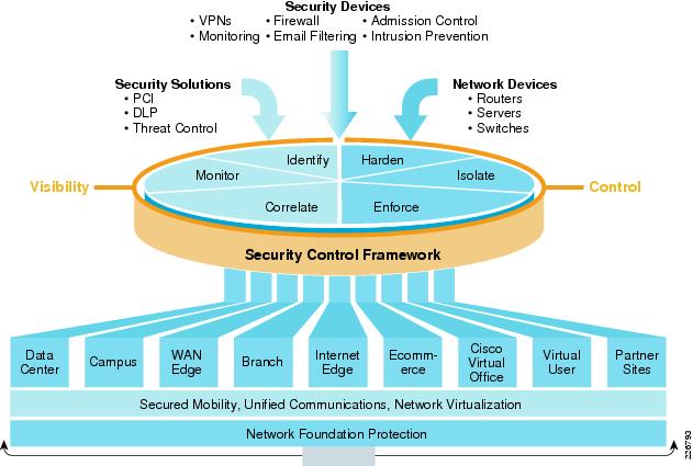
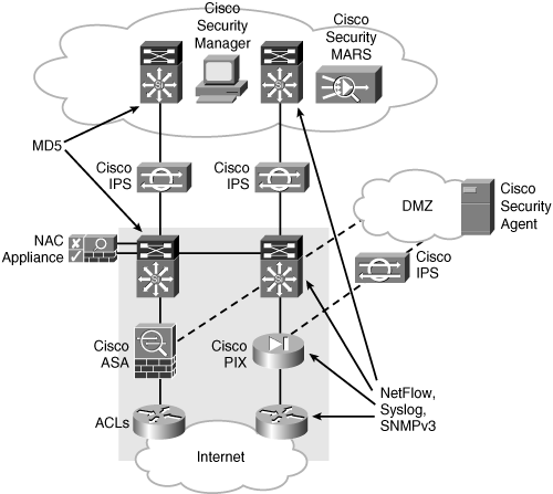
Total Visibility and Complete Control are two of main components of SCF (Security Control Framework). Network security is a function of visibility and control. Without visibility, there is a lack of control, and without control, you are missing key elements of security. The success of a security policy depends on solid visibility and control. Within SCF, there are 6 security actions used to enforce security policy and allow for visibility and control. Visibility is improved with identify, monitor, and correlate security actions; and control is enhanced through the harden, isolate, and enforce security actions. Each of these security actions is further defined in the SCF model.

Trust and Identity Technologies:

ACL
Firewall
Cisco Network Admission Control (NAC) Appliance
802.1X
Cisco Identity-Based Network Services (IBNS)


802.1X and EAPoL


Detecting and Mitigating Threats

Endpoint protection
Application security and content security defense
Infection containment
Inline IPS and anomaly detection


Threat Detection and Mitigation Technologies

Here are some examples of Cisco threat-detection and threat-mitigation technologies:
  • FWSM: Catalyst 6500 Firewall Services Module
  • ASA: Adaptive Security Appliance (Robust firewall or NIPS)
  • IOS firewall: Cisco IOS software feature set
  • IPS sensor appliance: NIPS
  • IPS: Intrusion prevention system (IOS feature)
  • NAC: Cisco NAC Appliance
  • Cisco Traffic Anomaly Detector Module: Detects high-speed DoS attacks
  • Cisco IronPort Web Security Appliance (Cisco WSA)
  • Cisco IronPort Email Security Appliance (Cisco ESA)
  • Network management protocols and solutions
    • NetFlow: Stats on packets flowing through router (IOS feature)
    • Syslog: Logging data (IOS feature)
    • SNMP: Simple Network Management Protocol (IOS feature)
    • Cisco MARS: Monitoring, Analysis, and Response System
    • Remote Monitor (RMON) events
    • CPU and interface statistic
    • Cisco Security Manager
    • Cisco NAC Manager


Threat Detection and Mitigation


Security Management Applications

Security Platform Solutions:
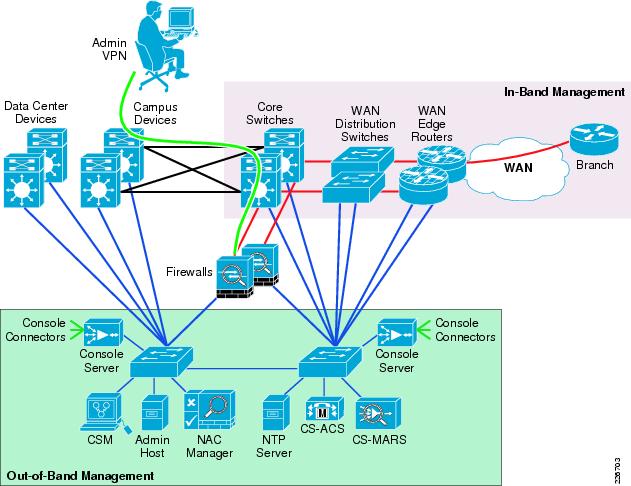
Cisco has a variety of security management products and technologies that allow scalable administration and enforcement of security policy for the Cisco SCF architecture. These solutions reduce the operational management and automate many of the common tasks, including configuration, analysis, incident response, and reporting. Security management platforms include the following:
  • Cisco Security Manager (CSM) is an integrated solution for GUI configuration management of firewall, VPN, and IPS policies on Cisco security appliances, firewalls, routers, and switch modules. CSM has capabilities for security policies to be deployed by device, by group, or globally for all devices.
  • Cisco Secure Access Control Server (ACS) provides centralized control for administrative access to Cisco devices and security applications. ACS provides for AAA security services and supports routers, switches, VPN services, ASAs, and Cisco NAC clients. In addition, Cisco ACS also supports back-end directory integration with Lightweight Directory Access Protocol (LDAP) and Microsoft Active Directory (AD) for authentication services.
  • Cisco Security Monitoring, Analysis, and Response System (Cisco Security MARS) tor, identify, isolate, and respond to security threats. MARS understands the network topology and device configurations from routers, switches, firewalls, and IPS devices. MARS also can model packet flows on the network.
  • Cisco NAC Manager is an appliance that manages the Cisco NAC servers. NAC Manager has a web-based interface for managing security policies and online users that are part of the NAC infrastructure. Cisco NAC Manager acts as an authentication proxy using Cisco ACS or Microsoft AD.
  • System Administration Host provides a centralized host used to stage configuration, software images, and implement network changes.
  • Network Time Protocol (NTP) server provides time synchronization to NTP clients such as routers and switches. Time synchronization is crucial in the analysis of event correlations.
  • Configuration and Software Archive Host serves as a repository to backup device configurations and software images.


SAFE Management Network: In-Band and Out-of-Band
Integrated Security for Cisco IOS

Cisco IOS Integrated
Security Description
Cisco IOS firewall
Stateful multiservice application-based filtering
Cisco IOS IPS
Cisco IOS IPS Inline deep packet inspection
Cisco IOS IPsec
Data encryption at the packet level
Cisco IOS Trust and Identity
AAA, PKI, SSH, SSL

 Securing the Enterprise

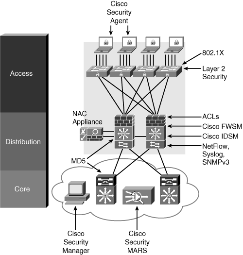
Implementing Security in the Campus

Cisco Security
Category
Security Solutions

Identity and access control
802.1X, NAC, ACLs, and firewalls
Threat detection and mitigation

NetFlow, syslog, SNMP, RMON, CS-MARS, and NIPS
Infrastructure protection
AAA, TACACS, RADIUS, SSH, NMPv3, IGP/EGP MD5, and Layer 2 security features
Security management
CSM, CS-MARS, and ACS


Enterprise Campus Security

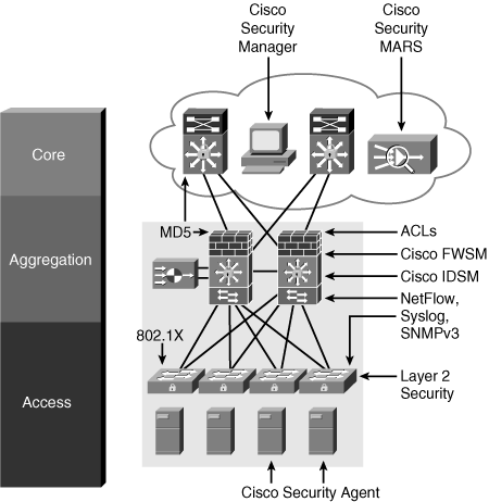
Security in the Data Center

Cisco Security
Category
Security Solutions

Identity and access control
802.1X, ACLs, and firewalls (FWSM
Threat detection and mitigation

NetFlow, syslog, SNMP, RMON, CS-MARS, and NIPS
Infrastructure protection
AAA, TACACS, RADIUS, SSH, SNMPv3, IGP/EGP MD5, and
Layer 2 security features
Security management
CSM, CS-MARS, and ACS


Enterprise Data Center Security

Security in the Enterprise Edg

Cisco Security
Category
Security Solutions

Identity and access control
Firewalls, IPsec, SSL VPN, and ACLs
Threat detection and mitigation

NetFlow, syslog, SNMP, RMON, IDS modules, CS-MARS, and NIPS
Infrastructure protection
AAA, CoPP, TACACS, RADIUS, SSH, SNMP v3, IGP/EGP MD5, RFC 2827 ingress filtering and Layer 2 security features
Security management
CSM, CS-MARS, and ACS


Enterprise Edge and WAN Security

Thursday, January 12, 2012

CCDA 640-864 Official Cert Guide - Chapter 12 Summary


Network Security Overview
U.S. Public Company Accounting Reform and Investor Protection Act of 2002 (Sarbanes-Oxley or SOX): Focuses on the accuracy and controls imposed on a company’s financial records. This was passed as a U.S. federal law because of a number of corporate and accounting scandals.

Payment Card Industry (PCI) Data Security Standard (DSS): PCI is a data security standard that defines how to protect credit card holder data, including the storage and transfer of credit card holder information. Many retailers that accept credit cards have to meet PCI DSS standards or pay stiff penalties and are subject to regular and rigorous audits for PCI DSS compliance.

Gramm-Leach-Bliley Financial Services Modernization Act of 1999 (GLBA): Provides protection against the sale of bank and account information that is regularly bought and sold by financial institutions. GLBA also guards against the practice of obtaining private information through false pretenses.

U.S. Health Insurance Portability and Accountability Act (HIPAA): Applies to the protection of private health information that is used electronically. The purpose is to enable better access to health information, reduce fraud, and lower the cost of health care in the United States.

EU Data Protection Directive 95/46/EC: Calls for the protection of people’s right to privacy with respect to the processing of personal data.
Reconnaissance: The goal of reconnaissance is to gather as much information as possible about the target host/network. Generally, this type of information gathering is done before an attack is carried out.

Gaining unauthorized access: Refers to the act of attacking or exploiting the target system or host. Operating systems, services, and physical access to the target host have known system vulnerabilities that the attacker can take advantage of and use to increase his or her privileges. Social engineering is another technique for obtaining confidential information from employees by manipulation. As a result of the attacker exploiting the host, confidential information can be read, changed, or deleted from the system.

Denial of service (DoS): DoS attacks aim to overwhelm resources such as memory, CPU, and bandwidth and thus impact the target system and deny legitimate user’s access. Distributed DoS (DDoS) attacks involve multiple sources working together to deliver the attack.

Feature Description
Feature
Verifies DHCP transitions and prevents rogue DHCP server from interfering with production traffic
DHCP snooping

Intercepts Address Resolution Protocol (ARP) packets and verifies that the packets have valid IP-to-MAC bindings
Dynamic ARP Inspection
(DAI)
Prevents unknown source addresses from using the network as a transport mechanism to carry out attacks
Unicast Reverse Path Forwarding (uRFP)

Controls what traffic is allowed on the network
Access control lists (ACL)

Controls the rate of bandwidth that incoming traffic, such as
ARP packets and DHCP requests
Rate limiting


When attackers change sensitive data without the proper authorization, this is called an integrity violation.

Confidentiality breaches occur when the attacker attempts to read sensitive information.

Security Policy and Process


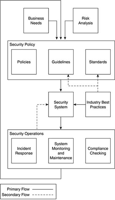
Basic Approach of a Security Policy:
To help create a security policy, here is generally accepted approach from RFC 2196:
Step 1. Identify what you are trying to protect.
Step 2. Determine what you are trying to protect it from.
Step 3. Determine how likely the threats are.
Step 4. Implement measures that protect your assets in a cost-effective manner.
Step 5. Review the process continuously, and make improvements each time a weakness is found


PKI
  • It relies on asymmetric cryptography, which uses two different keys for encryption.
  • Public keys are used to encrypt and private keys to decrypt.
  • PKI requires a certificate to be issued by a certificate authority (CA) and is used by many e-commerce sites on the Internet.

VPN Description
VPN Name
Use AH and ESP to secure data; requires endpoints have IPsec software
Standard IPsec

Secure encrypted point-to-point GRE tunnels; on-demand spoke-to-spoke connectivity
Cisco DMVPN

Simplifies hub-and-spoke VPNs; need to reduce VPN management
Cisco Easy VPN
Enables routing and multicast traffic across an IPsec VPN; non-IP protocol and QoS support
Cisco GRE-based VPN
Encryption integration on IP and MPLS WANs; simplifies encryption
management using group keying; any-to-any connectivity
Cisco GET VPN


The IPsec suite is an open standard. IPsec uses the following protocols to perform various functions:
  • Authentication Headers (AH) provide connectionless integrity and data origin authentication for IP datagram’s and provides protection against replay attacks.
  • Encapsulating Security Payloads (ESP) provide confidentiality, data origin authentication, connectionless integrity, an anti-replay service (a form of partial sequence integrity), and limited traffic flow confidentiality.


Tuesday, January 10, 2012

CCDA 640-864 Official Cert Guide - Chapter 11 Summary


OSPFv2 Areas

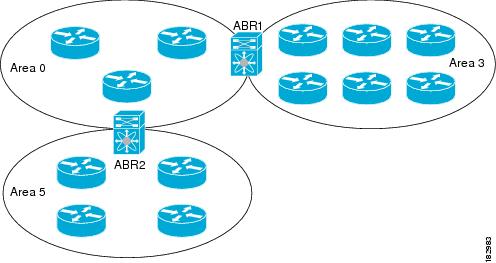
You can limit the CPU and memory requirements that OSPFv2 puts on the routers by dividing an OSPFv2 network into areas. An area is a logical division of routers and links within an OSPFv2 domain that creates separate subdomains. LSA flooding is contained within an area, and the link-state database is limited to links within the area. You can assign an area ID to the interfaces within the defined area. The Area ID is a 32-bit value that you can enter as a number or in dotted decimal notation, such as 10.2.3.1.
If you define more than one area in an OSPFv2 network, you must also define the backbone area, which has the reserved area ID of 0. If you have more than one area, then one or more routers become area border routers (ABRs). An ABR connects to both the backbone area and at least one other defined area.


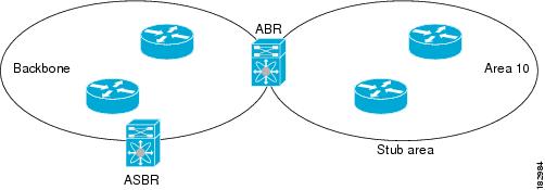
Stub Area
You can limit the amount of external routing information that floods an area by making it a stub area. A stub area is an area that does not allow AS External (type 5) LSAs. These LSAs are usually flooded throughout the local autonomous system to propagate external route information. Stub areas have the following requirements:
•All routers in the stub area are stub routers.
•No ASBR routers exist in the stub area.
•You cannot configure virtual links in the stub area.


Stub areas use a default route for all traffic that needs to go through the backbone area to the external autonomous system. The default route is 0.0.0.0 for IPv4.

Not-So-Stubby Area
A Not-so-Stubby Area (NSSA) is similar to a stub area, except that an NSSA allows you to import autonomous system external routes within an NSSA using redistribution. The NSSA ASBR redistributes these routes and generates NSSA External (type 7) LSAs that it floods throughout the NSSA. You can optionally configure the ABR that connects the NSSA to other areas to translate this NSSA External LSA to AS External (type 5) LSAs. The ABR then floods these AS External LSAs throughout the OSPFv2 autonomous system. The backbone Area 0 cannot be an NSSA.


OSPF Router Types

The ABR has a separate link-state database for each area to which it connects. The ABR sends Network Summary (type 3) LSAs from one connected area to the backbone area. The backbone area sends summarized information about one area to another area.
OSPFv2 defines one other router type: the autonomous system boundary router (ASBR). This router connects an OSPFv2 area to another autonomous system. An autonomous system is a network controlled by a single technical administration entity. OSPFv2 can redistribute its routing information into another autonomous system or receive redistributed routes from another autonomous system.

LSA Types

Type
Name
Description
1
Router LSA
LSA sent by every router. This LSA includes the state and the cost of all links and a list of all OSPFv2 neighbors on the link. Router LSAs trigger an SPF recalculation. Router LSAs are flooded to local OSPFv2 area.
2
Network LSA
LSA sent by the DR. This LSA lists all routers in the multi-access network. Network LSAs trigger an SPF recalculation.
3
Network Summary LSA
LSA sent by the area border router to an external area for each destination in the local area. This LSA includes the link cost from the area border router to the local destination.
4
ASBR Summary LSA
LSA sent by the area border router to an external area. This LSA advertises the link cost to the ASBR only.
5
AS External LSA
LSA generated by the ASBR. This LSA includes the link cost to an external autonomous system destination. AS External LSAs are flooded throughout the autonomous system.
7
NSSA External LSA
LSA generated by the ASBR within a not-so-stubby area (NSSA). This LSA includes the link cost to an external autonomous system destination. NSSA External LSAs are flooded only within the local NSSA.
9-11
Opaque LSAs
LSA used to extend OSPF.


OSPFv2 Summary
OSPFv2 is used in large enterprise IPv4 networks. The network topology must be hierarchy. The characteristics of OSPFv2 follow:
  • Link-state routing protocol.
  • Uses IP protocol 89.
  • Classless protocol (supports VLSMs and CIDR).
  • Metric is cost (based on interface bandwidth by default).
  • Fast convergence. Uses link-state updates and SPF calculation.
  • Reduced bandwidth use. Sends partial route updates only when changes occur.
  • Routes are labeled as intra-area, interarea, external Type 1, or external Type 2.
  • Support for authentication.
  • Uses the Dijkstra algorithm to calculate the SPF tree.
  • Default administrative distance is 110.
  • Uses multicast address 224.0.0.5 (ALLSPFRouters).
  • Uses multicast address 224.0.0.6 (ALLDRouters).
  • Good scalability. Recommended for large networks.

OSPFv3 Changes from OSPFv2:
The following are the major changes for OSPFv3:
  • Version number is 3: Obviously, this is a newer version of OSPF, and it runs over IPv6 only.
  • Support for IPv6 addressing: New LSAs created to carry IPv6 addresses and prefixes.
  • Per-link processing: OSPFv2 uses per-subnet processing. With link processing, routers in the same link can belong to multiple subnets.
  • Address semantics removed: Addresses are removed from the router and network LSAs. These LSAs now provide topology information.
  • No authentication in the OSPFv3 protocol: schemes inherited in IPv6.
  • New link LSA: For local-link flooding scope.
  • New intra-area-prefix LSA: Carries all the IPv6 prefix information. Similar to OSPFv2 router and network LSAs.
  • Identifying neighbors by router ID: Neighbors are always identified by the router ID. This does not occur in OSPFv2 point-to-point and broadcast networks.
  • Options field changes: Two Options bits, the R-bit and the V6-bit, have been added to the Options field for processing router LSAs during the SPF calculation.

OSPFv3 LSA Types


Router LSA:
Each OSPF router originates Router LSAs indicating the state and cost of the router's interfaces to the area. Router LSAs are flooded throughout the single area only.
A router may originate one or more Router LSAs, distinguished by their Link State IDs. The receiving router concatenates the Router LSAs if it receives more than one Router LSA from a single router.
The Router LSA indicates if the router is an ASBR or an ABR or if it is one end-point of a virtual link. These LSAs have no address information.


Network LSA:
Network LSAs are originated by the DR for a broadcast or NBMA network in the area which supports two or more routers. The LSA describes all routers connected to the link, including the DR. The LSA's Link State ID field is set to the Interface ID that the DR has been using in Hello packets. No address information is carried in the Network LSA.


Inter-Area Prefix LSA:
These LSAs are IPv6 equivalent of IPv4's Type-3 Summary LSAs. These LSAs are originated by the ABR to specify IPv6 prefixes that belong to other areas. A separate LSA is originated for each address prefix.
For Stub areas, the Inter-area Prefix LSA is used to describe a default route. The prefix length of the default route is set to 0.


Inter-Area Router LSA:
These LSAs are IPv6 equivalent of IPv4's Type-4 Summary LSAs. Originated by the ABR, the Inter-Area Router LSA describes the route to the ASBR. Each LSA describes a route to a single router.


AS-External LSA:
These LSAs are IPv6 equivalent of IPv4's Type-5 External LSAs. These LSAs are originated by ASBRs describing the destinations external to the AS. Each LSA describe a route to a single IPv6 prefix external to the AS.
AS-External LSAs can be used to describe a default route. Default routes are used when no specific route exists for a destination.


Link LSA:
A router originates a separate Link LSA for each link it is attached to. These LSAs have link-local flooding scope and are never flooded beyond a link that they are associated with. These LSAs have three purposes-
    - notify the link-local address of the router's interface to the routers attached to the link
    - inform other routers attached to the link of the list of IPv6 prefixes to associate with the link
    - allow the router to assert the collection of Option bits to associate with the Network LSA that will be originated for the link.
The Link-State ID is set to the Interface ID of link of the originating router.


Intra-Area Prefix LSA:

A router uses Intra-Area Prefix LSA to advertise IPv6 prefixes that are associated with
    a) the router itself (in IPv4, this was carried in Router LSA)
    b) an attached stub network segment (in IPv4, this was carried in Router LSA)
    c) an attached transit network segment (in IPv4, this was carried in Network LSA)
A router can originate multiple Intra-Area Prefix LSAs for each router or transit network; each LSA is distinguished by its Link State ID.


Options field:
The 24-bit Options field is included in Hello and DBD packets, and Router, Network and Inter-area Router LSAs. It enables OSPF routers to support optional capabilities, and to communicate their capabilities to other OSPF routers in the network. 


OSPFv3 Summary
OSPFv3 is used in large enterprise IPv6 networks. The network topology must be hierarchical. OSPF is used in the enterprise campus building access, distribution, and core layers. OSPF is also used in the enterprise data center, WAN/MAN, and branch offices.
The characteristics of OSPFv3 follow:
  • Link-state routing protocol for IPv6.
  • Uses IPv6 Next Header 89.
  • Metric is cost (based on interface bandwidth by default).
  • Sends partial route updates only when changes occur.
  • Routes are labeled as intra-area, interarea, external Type 1, or external Type 2.
  • Uses IPv6 for authentication.
  • Uses the Dijkstra algorithm to calculate the SPF tree.
  • Default administrative distance is 110.
  • Uses multicast address FF02::5 (ALLSPFRouters).
  • Uses multicast address FF02::6 (ALLDRouters).
  • Fast convergence, scalable, and reduces bandwidth.
  • Recommended for large IPv6 networks.

BGP Summary
The characteristics of BGP follow:
  • BGP is an Exterior Gateway Protocol (EGP) used in routing in the Internet. It is an interdomain routing protocol.
  • BGP is a path-vector routing protocol suited for strategic routing policies.
  • It uses TCP port 179 to establish connections with neighbors.
  • BGPv4 implements CIDR.
  • eBGP is used for external neighbors. It is used between different autonomous systems.
  • iBGP is used for internal neighbors. It is used within an autonomous system.
  • BGP uses several attributes in the routing-decision algorithm.
  • It uses confederations and route reflectors to reduce BGP peering overhead.

Route Manipulation

            PBR
            Route Summarization
            Route Redistribution
            Route Filtering
           

IP Multicast Review


IGMP

IGMP is a standard defined in RFC1112 for IGMPv1, in RFC2236 for IGMPv2 and in RFC3376 for IGMPv3. IGMP specifies how a host can register with a router in order to receive specific multicast traffic. 


CGMP

CGMP was first implemented by Cisco to restrain multicast traffic in a L2 network. Because a switch is, by essence, not capable of looking at L3 packets, it cannot distinguish an IGMP packet. With CGMP, the router provides the interface between the hosts. The routers "talk" IGMP, and the switches "talk" CGMP.


IGMP Snooping

IGMP snooping is another feature that allows you to directly capture IGMP frames. 
IGMP snooping, as implied by the name, is a feature that allows the switch to "listen in" on the IGMP conversation between hosts and routers. When a switch hears an IGMP report from a host for a given multicast group, the switch adds the host's port number to the GDA list for that group. And, when the switch hears an IGMP Leave, it removes the host's port from the CAM table entry.


Sparse Versus Dense Multicast 

The Dense approach assumes that the multicast group members are densely distributed throughout the network (many of the subnets contain at least one group member), all devices want to receive multicast traffic, and that bandwidth is plentiful. The Sparse approach to multicast routing assumes that multicast group members are sparsely distributed throughout the network, assumes received do not want to receive multicast traffic, and that bandwidth is not necessarily widely available.

Multicast Source and Shared Trees 

With source trees, the tree roots from the source of the multicast group and then expands throughout the network in spanning-tree fashion to the destination hosts. Source trees are also called shortest-path trees (SPT) because they create paths without having to go through a rendezvous point (RP).
Shared trees create the distribution tree’s root somewhere between the network’s source and receivers. The root is called the RP. The tree is created from the RP in spanning-tree fashion with no loops.

PIM 

PIM comes in two flavors: sparse mode (PIM-SM) and dense mode (PIM-DM). The first uses shared trees and RPs to reach widely dispersed group members with reasonable protocol bandwidth efficiency. The second uses source trees and reverse path forwarding (RPF) to reach relatively close group members with reasonable processor and memory efficiency in the network devices of the distribution trees.

DVMRP 

RFC 1075 describes DVMRP. It is the primary multicast routing protocol used in the multicast backbone (MBONE). The MBONE is used in the research community.