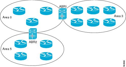
OSPFv2 Areas
You can limit the CPU and memory requirements that OSPFv2
puts on the routers by dividing an OSPFv2 network into areas. An
area is a logical division of routers and links within an OSPFv2 domain that
creates separate subdomains. LSA flooding is contained within an area, and the
link-state database is limited to links within the area. You can assign an area
ID to the interfaces within the defined area. The Area ID is a 32-bit value
that you can enter as a number or in dotted decimal notation, such as 10.2.3.1.
Stub Area
You can limit
the amount of external routing information that floods an area by making it a stub
area. A stub area is an area that does not allow AS External (type 5) LSAs. These
LSAs are usually flooded throughout the local autonomous system to propagate external
route information. Stub areas have the following requirements:
•No ASBR routers exist in the stub
area.
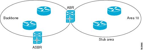
Stub areas use a default route for all traffic that needs to
go through the backbone area to the external autonomous system. The default
route is 0.0.0.0 for IPv4.
Not-So-Stubby Area
A
Not-so-Stubby Area (NSSA) is similar to a stub area, except that an NSSA allows
you to import autonomous system external routes within an NSSA using
redistribution. The NSSA ASBR redistributes these routes and generates NSSA
External (type 7) LSAs that it floods throughout the NSSA. You can optionally
configure the ABR that connects the NSSA to other areas to translate this NSSA
External LSA to AS External (type 5) LSAs. The ABR then floods these AS
External LSAs throughout the OSPFv2 autonomous system. The
backbone Area 0 cannot be an NSSA.
OSPF Router Types
The ABR has a separate link-state database for each area to
which it connects. The ABR sends Network Summary (type 3) LSAs from one
connected area to the backbone area. The backbone area sends summarized
information about one area to another area.
LSA Types
|
Type
|
||
OSPFv2 Summary
OSPFv2 is used in large enterprise IPv4 networks. The
network topology must be hierarchy. The characteristics of OSPFv2 follow:
- Link-state routing protocol.
- Uses IP protocol 89.
- Classless protocol (supports VLSMs and CIDR).
- Metric is cost (based on interface bandwidth by default).
- Fast convergence. Uses link-state updates and SPF calculation.
- Reduced bandwidth use. Sends partial route updates only when changes occur.
- Routes are labeled as intra-area, interarea, external Type 1, or external Type 2.
- Support for authentication.
- Uses the Dijkstra algorithm to calculate the SPF tree.
- Default administrative distance is 110.
- Uses multicast address 224.0.0.5 (ALLSPFRouters).
- Uses multicast address 224.0.0.6 (ALLDRouters).
- Good scalability. Recommended for large networks.
OSPFv3 Changes from OSPFv2:
The following are the major changes for OSPFv3:
- Version number is 3: Obviously, this is a newer version of OSPF, and it runs over IPv6 only.
- Support for IPv6 addressing: New LSAs created to carry IPv6 addresses and prefixes.
- Per-link processing: OSPFv2 uses per-subnet processing. With link processing, routers in the same link can belong to multiple subnets.
- Address semantics removed: Addresses are removed from the router and network LSAs. These LSAs now provide topology information.
- No authentication in the OSPFv3 protocol: schemes inherited in IPv6.
- New link LSA: For local-link flooding scope.
- New intra-area-prefix LSA: Carries all the IPv6 prefix information. Similar to OSPFv2 router and network LSAs.
- Identifying neighbors by router ID: Neighbors are always identified by the router ID. This does not occur in OSPFv2 point-to-point and broadcast networks.
- Options field changes: Two Options bits, the R-bit and the V6-bit, have been added to the Options field for processing router LSAs during the SPF calculation.
OSPFv3 LSA Types

Router LSA:
Each OSPF router originates Router LSAs indicating the state and cost of the router's interfaces to the area. Router LSAs are flooded throughout the single area only.
A router may originate one or more Router LSAs, distinguished by their Link State IDs. The receiving router concatenates the Router LSAs if it receives more than one Router LSA from a single router.
The Router LSA indicates if the router is an ASBR or an ABR or if it is one end-point of a virtual link. These LSAs have no address information.
Network LSA:
Network LSAs are originated by the DR for a broadcast or NBMA network in the area which supports two or more routers. The LSA describes all routers connected to the link, including the DR. The LSA's Link State ID field is set to the Interface ID that the DR has been using in Hello packets. No address information is carried in the Network LSA.
Inter-Area Prefix LSA:
These LSAs are IPv6 equivalent of IPv4's Type-3 Summary LSAs. These LSAs are originated by the ABR to specify IPv6 prefixes that belong to other areas. A separate LSA is originated for each address prefix.
For Stub areas, the Inter-area Prefix LSA is used to describe a default route. The prefix length of the default route is set to 0.
Inter-Area Router LSA:
These LSAs are IPv6 equivalent of IPv4's Type-4 Summary LSAs. Originated by the ABR, the Inter-Area Router LSA describes the route to the ASBR. Each LSA describes a route to a single router.
AS-External LSA:
These LSAs are IPv6 equivalent of IPv4's Type-5 External LSAs. These LSAs are originated by ASBRs describing the destinations external to the AS. Each LSA describe a route to a single IPv6 prefix external to the AS.
AS-External LSAs can be used to describe a default route. Default routes are used when no specific route exists for a destination.
Link LSA:
A router originates a separate Link LSA for each link it is attached to. These LSAs have link-local flooding scope and are never flooded beyond a link that they are associated with. These LSAs have three purposes-
- notify the link-local address of the router's interface to the routers attached to the link
- inform other routers attached to the link of the list of IPv6 prefixes to associate with the link
- allow the router to assert the collection of Option bits to associate with the Network LSA that will be originated for the link.
The Link-State ID is set to the Interface ID of link of the originating router.
Intra-Area Prefix LSA:
A router uses Intra-Area Prefix LSA to advertise IPv6 prefixes that are associated with
a) the router itself (in IPv4, this was carried in Router LSA)
b) an attached stub network segment (in IPv4, this was carried in Router LSA)
c) an attached transit network segment (in IPv4, this was carried in Network LSA)
A router can originate multiple Intra-Area Prefix LSAs for each router or transit network; each LSA is distinguished by its Link State ID.
Options field:
OSPFv3 Summary
OSPFv3 is used in large enterprise IPv6 networks. The
network topology must be hierarchical. OSPF is used in the enterprise campus
building access, distribution, and core layers. OSPF is also used in the
enterprise data center, WAN/MAN, and branch offices.
The characteristics of OSPFv3 follow:
- Link-state routing protocol for IPv6.
- Uses IPv6 Next Header 89.
- Metric is cost (based on interface bandwidth by default).
- Sends partial route updates only when changes occur.
- Routes are labeled as intra-area, interarea, external Type 1, or external Type 2.
- Uses IPv6 for authentication.
- Uses the Dijkstra algorithm to calculate the SPF tree.
- Default administrative distance is 110.
- Uses multicast address FF02::5 (ALLSPFRouters).
- Uses multicast address FF02::6 (ALLDRouters).
- Fast convergence, scalable, and reduces bandwidth.
- Recommended for large IPv6 networks.
BGP Summary
The characteristics of BGP follow:
- BGP is an Exterior Gateway Protocol (EGP) used in routing in the Internet. It is an interdomain routing protocol.
- BGP is a path-vector routing protocol suited for strategic routing policies.
- It uses TCP port 179 to establish connections with neighbors.
- BGPv4 implements CIDR.
- eBGP is used for external neighbors. It is used between different autonomous systems.
- iBGP is used for internal neighbors. It is used within an autonomous system.
- BGP uses several attributes in the routing-decision algorithm.
- It uses confederations and route reflectors to reduce BGP peering overhead.
Route Manipulation
PBR
Route
Summarization
Route
Redistribution
Route
Filtering
IP Multicast Review
IGMP
IGMP is a standard defined in RFC1112 for IGMPv1, in RFC2236
for IGMPv2 and in RFC3376 for IGMPv3. IGMP specifies how a host can register
with a router in order to receive specific multicast traffic.
CGMP
CGMP was first implemented by Cisco to restrain multicast
traffic in a L2 network. Because a switch is, by essence, not capable of
looking at L3 packets, it cannot distinguish an IGMP packet. With CGMP, the router
provides the interface between the hosts. The routers "talk" IGMP,
and the switches "talk" CGMP.
IGMP Snooping
IGMP snooping is another feature that allows you to directly
capture IGMP frames.
IGMP snooping, as implied by the name, is a feature that
allows the switch to "listen in" on the IGMP conversation between
hosts and routers. When a switch hears an IGMP report from a host for a given
multicast group, the switch adds the host's port number to the GDA list for
that group. And, when the switch hears an IGMP Leave, it removes the host's
port from the CAM table entry.
Sparse Versus Dense Multicast
The Dense approach assumes
that the multicast group members are densely distributed throughout the network
(many of the subnets contain at least one group member), all devices want to
receive multicast traffic, and that bandwidth is plentiful. The Sparse approach
to multicast routing assumes that multicast group members are sparsely
distributed throughout the network, assumes received do not want to receive
multicast traffic, and that bandwidth is not necessarily widely available.
Multicast Source and Shared Trees
With source trees, the
tree roots from the source of the multicast group and then expands throughout
the network in spanning-tree fashion to the destination hosts. Source trees are
also called shortest-path trees (SPT) because they create paths without having
to go through a rendezvous point (RP).
Shared trees create the distribution tree’s root somewhere
between the network’s source and receivers. The root is called the RP. The tree
is created from the RP in spanning-tree fashion with no loops.
PIM
PIM comes in two flavors: sparse mode (PIM-SM) and
dense mode (PIM-DM). The first uses shared trees and RPs to reach widely
dispersed group members with reasonable protocol bandwidth efficiency. The
second uses source trees and reverse path forwarding (RPF) to reach relatively
close group members with reasonable processor and memory efficiency in the
network devices of the distribution trees.
DVMRP
RFC 1075 describes DVMRP. It is the primary
multicast routing protocol used in the multicast backbone (MBONE). The MBONE is
used in the research community.
No comments:
Post a Comment